You are using an out of date browser. It may not display this or other websites correctly.
You should upgrade or use an alternative browser.
You should upgrade or use an alternative browser.
A slow way into a Castle...........
- Thread starter John TAYLOR
- Start date
OzzyO
Western Thunderer
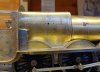
In this drawing you can see the inside steam pipe on the left hand side of the left of the head on drawing. I'm not sure if it was the same on the R/H side? Having had anther look at the drawing it has, it looks like the inside cylinder steam pipes are the two flanges closer to the centre of the loco.

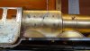
In this photo you can see the inside steam pipe mounting plate as the round plate at the front,you can also see the two exhausts one for the inside cylinders (front) and the outside cylinder (rear). The square bracket below the saddle is for the exhaust steam pipe to the exhaust steam injector.

Maybe I should have used this photo to show the saddle shape, It has the stepped top to the inside of the inside valve cover your loco does not have this and depending on the time your building the loco it could have the Mec. lub box in front of the steam pipe as in the bottom photo.


In all of the photos I have of Castles I have not seen a saddle that looks like the casting in your kit.
All photos are copyright and are used to show some points.
OzzyO.
In this photo you can see the inside steam pipe mounting plate as the round plate at the front,you can also see the two exhausts one for the inside cylinders (front) and the outside cylinder (rear). The square bracket below the saddle is for the exhaust steam pipe to the exhaust steam injector.
Maybe I should have used this photo to show the saddle shape, It has the stepped top to the inside of the inside valve cover your loco does not have this and depending on the time your building the loco it could have the Mec. lub box in front of the steam pipe as in the bottom photo.
In all of the photos I have of Castles I have not seen a saddle that looks like the casting in your kit.
All photos are copyright and are used to show some points.
OzzyO.
OzzyO
Western Thunderer
Great picture Ozzy and makes sense that the middle cylinders would have a single steam pipe..
JB.
Hello JB, I've had a better look at the drawing and it has four flange plates showing on the superheat header. Two steam pipes for the out side and two steam pipes for the inside cylinders.
OzzyO.
OzzyO
Western Thunderer
Thanks Ozzy, just meant single entry to the pair of inside cylinders, or was it a monoblock?
Would I be right in thinking that the double chimney engines didn't have lifting rings on the blast pipes? Can't see them on the drawing..
JB.
Hello J.B. AFAIK the inside cylinders were a one piece casting that was bolted to the frames, if it had been a two part casting it would have had a very large flange plate for all the bolts Etc. It would have also involved making two patters for making the mould for the cylinders.
If what your talking about is "Jumper" blast pipe tops I don't think that the Castles had them fitted. When you look at the drawing it looks like the Castles could have had double blower rings around the blast pipe, one feeding from the front and one feeding from the rear, with the main feed coming in at about 3" to the rear of the centre of the twin blast-pipe.
OzzyO.
John TAYLOR
Western Thunderer
Having studied all your pics and examples concerning the smokebox saddle it was obvious that I had limited options with a large and incorrect saddle casting. I sharpened up a small screwdriver into a chisel and removed some of the saddle front in situ......

Then it was a case of some improvisation and subtifuge to make things a little better........

still needs some tidying and filling but its the best I could come up with.......

Then it was a case of some improvisation and subtifuge to make things a little better........
still needs some tidying and filling but its the best I could come up with.......
John TAYLOR
Western Thunderer
Thanks OzzyO
Yep, they were hidden on two separate etches....duh!
John
Yep, they were hidden on two separate etches....duh!
John
John TAYLOR
Western Thunderer
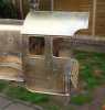
Moved on to the cab roof this week...

and repositioned the boiler washout plugs the top row of which were all too low


Finally realised that the front cylinder cover relates to early 1950`s and needed to be a rounded top for the 1930 period I`m basing mine on.

and repositioned the boiler washout plugs the top row of which were all too low
Finally realised that the front cylinder cover relates to early 1950`s and needed to be a rounded top for the 1930 period I`m basing mine on.
Attachments
John TAYLOR
Western Thunderer
Time to stop playing trains and return to this ongoing project.......... so where was I ?

So far she runs through a B6 turnout with no front bogie problems but then the springs are not fully supressed yet

With all the details and gubbins between frames I`m not going to be able to apply my preferred choice of pickups....... so there is only one option for me and that is to use sprung pickups.
I`ve never really got on with them but I`ve decided to try Slaters having read Jim McGeown`s advice on them.....

Nice... but I was`nt happy with the springs which seem either too short or the hole in the housing is too deep. Either way they seem far too weak to provide strong enough contact on the rear of the wheel tread , especially after adding the pickup wiring as the springs are not strong enough to overcome any pull they might impart.......
So I decided to carefully pull the springs on the plunger shafts to make them at least as long as the non threaded part of the plunger shank

This has made me more confident about their effectiveness..........
As you can see.... the lower of these two is just the spring as provided, whereby there is no strenght to the spring until it is flush with the face of the housing. The upper is after fettling the spring length.

Overall I`ve now got a working set of four as I`m only going to apply to two driven axles with two tender axles using my preferred system.

Now to drill the holes in the chassis frames................
So far she runs through a B6 turnout with no front bogie problems but then the springs are not fully supressed yet
With all the details and gubbins between frames I`m not going to be able to apply my preferred choice of pickups....... so there is only one option for me and that is to use sprung pickups.
I`ve never really got on with them but I`ve decided to try Slaters having read Jim McGeown`s advice on them.....
Nice... but I was`nt happy with the springs which seem either too short or the hole in the housing is too deep. Either way they seem far too weak to provide strong enough contact on the rear of the wheel tread , especially after adding the pickup wiring as the springs are not strong enough to overcome any pull they might impart.......
So I decided to carefully pull the springs on the plunger shafts to make them at least as long as the non threaded part of the plunger shank
This has made me more confident about their effectiveness..........
As you can see.... the lower of these two is just the spring as provided, whereby there is no strenght to the spring until it is flush with the face of the housing. The upper is after fettling the spring length.
Overall I`ve now got a working set of four as I`m only going to apply to two driven axles with two tender axles using my preferred system.
Now to drill the holes in the chassis frames................
Last edited:
Dog Star
Western Thunderer
I have the same opinion about a need for stronger springs so I replace the Phosphor Bronze springs by Slater's steel springs from the sprung hornguide / axlebox packs for locos. Same length, same coil diameter, same number of coils and same wire diameter... just made of Steel rather than PB.With all the details and gubbins between frames I`m not going to be able to apply my preferred choice of pickups....... so there is only one option for me and that is to use sprung pickups. I`ve never really got on with them but I`ve decided to try Slaters having read Jim Mcgowan`s advice on them.....
I was`nt happy with the springs which seem either too short or the hole in the housing is too deep. Either way they seem far too week to provide strong enough contact on the rear of the wheel tread , especially after adding the pickup wiring as the springs are not strong enough to overcome any pull they might impart.......
John TAYLOR
Western Thunderer
Thanks for that....... I did consider for a nano second whether to give Slaters a ring..... As it was I did Google `problems with sprung pickups` there were plenty of references to using Slaters pickups but no mention of weakness of springs.....
Scale7JB
Western Thunderer
Personally I think the springs are okay, but I do what Jim McGeown suggests which is o put a flat on the nose of the brass plunger giving a bigger surface area, and then using wet and dry polish the plunger and the backs of the wheels..
To be honest if I were building this castle I would dispense entirely with 'any' pickups on the engine and use 3 split axles on the tender.. Almost as infallible as battery power..
JB.
To be honest if I were building this castle I would dispense entirely with 'any' pickups on the engine and use 3 split axles on the tender.. Almost as infallible as battery power..
JB.
John TAYLOR
Western Thunderer
Now that JB would be a very tidy solution.....sadly beyond my skills.....
John TAYLOR
Western Thunderer
Thanks for your vote of confidence JB..... it`s certainly worth me considering before retro fitting these sprung pickups....
If someone here could explain....in simple terms......
If someone here could explain....in simple terms......
Dan Randall
Western Thunderer
Here you go....
Split axle pick-up in 0-gauge, Page 1
Split axle pick-up in 0-gauge, Page 2
Split axle pick-up in 0-gauge, Page 3
Regards
Dan
Split axle pick-up in 0-gauge, Page 1
Split axle pick-up in 0-gauge, Page 2
Split axle pick-up in 0-gauge, Page 3
Regards
Dan
Last edited:
John TAYLOR
Western Thunderer
......................................................... ..........................................................
..........................................................Steph Dale
Western Thunderer
Thanks JB, Dan, My effect remains subtle but far-reaching...!
John,
If you're going to Kettering I'll be there and more than happy tobore you to tears discuss split axles with you.
Steph
John,
If you're going to Kettering I'll be there and more than happy to
Steph