Stuart Birks
Active Member
For controlling the points and signals on Acorn Wood I had originally intended to use simple switches triggering the MERG servo controller boards. I then thought that it would be more pleasent to operate switches that looked like signal box levers and then by extension it would be fun to have some form of interlocking.
I made a very crude test piece for proof of concept and it worked very well.

As this was a success I looked for levers and lever frames. I decided that the lever frame by Model Signal Engineering looked the nicest so I bought a 7 lever kit. The levers are cast brass and with a bit of work look very good. I was much less happy with the rest of the kit.

This is the frame built with one lever fitted with the latch handle. There are many things tat I did not like so I decided to make my own frame. Luckily MSE (Now wizard models) sell the lever casting as a seperate item so I was able to buy just what I wanted.
This is one of my completed levers. I basically made all the components. I also drilled out the hole and bushed it as it was just a cast hole. This is the one thing I wish I had done diferently. Although bushing it removed all the slop The hole was not accuratly placed. This has resulted in the final row of levers not sitting in a perfectly even line. I should have nade a jig to clamp the levers in a consistent place and then gone through with an end mill so they were consistent. Look at the lever frame on David Waite's thread A layout called CHIMTONSTOKE to see how it should have been done.

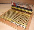
The frame was made from various bits of brass sheet and strip and came out very well. The curved plates wer rolled and then a jig made so that I could mill the latch slots in a consistent place.

The interlocking frame was also milled to support the brass slider bars.

Connecting bars were made using 2mm rod threaded at each end. This means that 1 turn of the end connector would give 0.4mm of adjustment, this is effectivly +/- 0.2mm so is perfectly adequate.

Microbreak switches were mounted at the end of the frame to give the electrical switching.

When I first tried operating it the bars would not slide well and the locking jamed up. This turned out to be caused by the brass bars not being straight. A silly assumption to make. With a bit of carefull straightening at all works beautifully with very limited movement on the lever before realising it is locked or a nice light movement if it isn't even wher it is having to move several locking bars.
Even the spare levers are switched and fully wired right through to a connector on the layout board so can be activated and used for something if I want to. Part way through this process I decided that the MERG servo boards were going to be quite expensive and so I changed to using an Arduino board. This give me all the control I want even giving variable levels of bounce on the signal arms depending on the distance from the signal box.
This is the final control panel, finished to look a bit like a signal box.

I have deliberatly not implemented all locking rules. This enables me to operate it in a simplified play mode if I ignore the signals and facing point locks. If I want to include the signalling then it is necessary to operate it in the correct manner.
Stuart
I made a very crude test piece for proof of concept and it worked very well.
As this was a success I looked for levers and lever frames. I decided that the lever frame by Model Signal Engineering looked the nicest so I bought a 7 lever kit. The levers are cast brass and with a bit of work look very good. I was much less happy with the rest of the kit.
This is the frame built with one lever fitted with the latch handle. There are many things tat I did not like so I decided to make my own frame. Luckily MSE (Now wizard models) sell the lever casting as a seperate item so I was able to buy just what I wanted.
This is one of my completed levers. I basically made all the components. I also drilled out the hole and bushed it as it was just a cast hole. This is the one thing I wish I had done diferently. Although bushing it removed all the slop The hole was not accuratly placed. This has resulted in the final row of levers not sitting in a perfectly even line. I should have nade a jig to clamp the levers in a consistent place and then gone through with an end mill so they were consistent. Look at the lever frame on David Waite's thread A layout called CHIMTONSTOKE to see how it should have been done.
The frame was made from various bits of brass sheet and strip and came out very well. The curved plates wer rolled and then a jig made so that I could mill the latch slots in a consistent place.
The interlocking frame was also milled to support the brass slider bars.
Connecting bars were made using 2mm rod threaded at each end. This means that 1 turn of the end connector would give 0.4mm of adjustment, this is effectivly +/- 0.2mm so is perfectly adequate.
Microbreak switches were mounted at the end of the frame to give the electrical switching.
When I first tried operating it the bars would not slide well and the locking jamed up. This turned out to be caused by the brass bars not being straight. A silly assumption to make. With a bit of carefull straightening at all works beautifully with very limited movement on the lever before realising it is locked or a nice light movement if it isn't even wher it is having to move several locking bars.
Even the spare levers are switched and fully wired right through to a connector on the layout board so can be activated and used for something if I want to. Part way through this process I decided that the MERG servo boards were going to be quite expensive and so I changed to using an Arduino board. This give me all the control I want even giving variable levels of bounce on the signal arms depending on the distance from the signal box.
This is the final control panel, finished to look a bit like a signal box.
I have deliberatly not implemented all locking rules. This enables me to operate it in a simplified play mode if I ignore the signals and facing point locks. If I want to include the signalling then it is necessary to operate it in the correct manner.
Stuart