A Layout Called CHIMTONSTOKE

David Waite

Western Thunderer
I bet you've got dovetail joints somewhere on that baseboard carpentry. - Wow. :) I'm just building some baseboards myself at the moment and I don't know if I should ever show my poor efforts. :)

Jim.
Dovetails absolutely NO I hate them half joints and screws everywhere, I call it cheating, some are in the pipe line for a next project but I’m trying not to think of them.
Please do share the construction of your baseboards, I have made one massive design fault with most of my base boards and that is, the only way they can ever be taken out of the attic is to cut them up into small pieces.
David.
 

David Waite

Western Thunderer
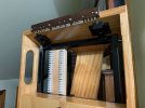
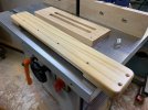
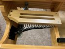
I have been busy and progressing slowly along, a piece of wood was screwed to the top of the steel frame for the screw terminal blocks to be mounted on.
IMG_1584.jpeg


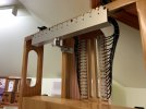
Next the wiring and was this a challenge I'm not good at doing things at arms length just cannot focus anymore so up and down the steps a few times for every wire, cutting the lengths then tinning the ends, then fitting them in place and then soldering them to their brass terminals I was glad when it was all completed.
IMG_1589.jpeg


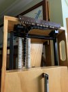
No two solder joints look the same but all good joints no dry ones, wax cord was used to hold all the wires tightly together.
IMG_1592.jpeg


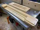
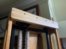
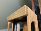
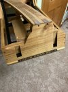
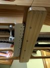
Next the timber cover was made, the only pine I had which was thick enough that I could machine down to the sizes I wanted was a piece of 90x45 framing pine, it had been in the shed for a number of years and quite dry so I hope it won't shrink any further, I painted it with three coats of Clear Satin polyurethane which should seal it and help to stabilise it.
IMG_1632.jpeg


IMG_1631.jpeg


The timber cover was a firm fit over the Fibre Board and all fitted nicely together.
IMG_1633.jpeg


IMG_1636.jpeg


IMG_1642.jpeg


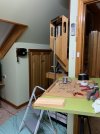
I can walk through the gap now without getting my clothing hooked in it.
IMG_1639.jpeg
 

David Waite

Western Thunderer
Still busy I wanted to get both halves of the contact assemblies wired to their screw terminal blocks before Christmas and I have managed to achieve it.
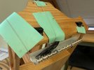
I hung the contact side from string to give me better access for soldering.
IMG_1666.jpeg


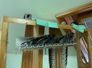
All wired and tied up to stop any movement which could cause damage to the copper contacts.
IMG_1673.jpeg


All finished.
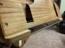
IMG_1675.jpeg


The two slots are for the wires to pass through from the base board, I managed to pick up some more screw terminal blocks today so I
can continue on wiring both lift up sections to their base boards when I feel like it.
IMG_1676.jpeg

Looking up from underneath
IMG_1685.jpeg


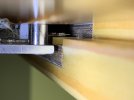
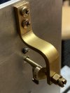
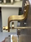
I lost count on how many shots I took to get a clear picture in this tiny gap this photo was the best one,
The adjustment linkage worked well and as can be seen there is a slight pressure of the contact on the brass terminal from its horizontal position.
IMG_1678.jpeg
Well this is up to date of where I'm at with the layout, I am hoping to start some track work on the lift up sections well that's the plan but who knows what excuses I can come up with like some more Instruments.

So from Me, I Wish you all a Safe and Joyful Christmas where ever you go or what ever you do.
David.
 

jonte

Western Thunderer
Still busy I wanted to get both halves of the contact assemblies wired to their screw terminal blocks before Christmas and I have managed to achieve it.
I hung the contact side from string to give me better access for soldering.
View attachment 204531


All wired and tied up to stop any movement which could cause damage to the copper contacts.
View attachment 204532


All finished.
View attachment 204534


The two slots are for the wires to pass through from the base board, I managed to pick up some more screw terminal blocks today so I
can continue on wiring both lift up sections to their base boards when I feel like it.
View attachment 204535

Looking up from underneath
View attachment 204536


I lost count on how many shots I took to get a clear picture in this tiny gap this photo was the best one,
The adjustment linkage worked well and as can be seen there is a slight pressure of the contact on the brass terminal from its horizontal position.
View attachment 204537
Well this is up to date of where I'm at with the layout, I am hoping to start some track work on the lift up sections well that's the plan but who knows what excuses I can come up with like some more Instruments.

So from Me, I Wish you all a Safe and Joyful Christmas where ever you go or what ever you do.
David.

I can only describe your art as ‘Museum Standard’ David.

Quite extraordinary.

Merry Christmas to you too.

Jon
 

James Spooner

Western Thunderer
Still busy I wanted to get both halves of the contact assemblies wired to their screw terminal blocks before Christmas and I have managed to achieve it.
I hung the contact side from string to give me better access for soldering.
View attachment 204531


All wired and tied up to stop any movement which could cause damage to the copper contacts.
View attachment 204532


All finished.
View attachment 204534


The two slots are for the wires to pass through from the base board, I managed to pick up some more screw terminal blocks today so I
can continue on wiring both lift up sections to their base boards when I feel like it.
View attachment 204535

Looking up from underneath
View attachment 204536


I lost count on how many shots I took to get a clear picture in this tiny gap this photo was the best one,
The adjustment linkage worked well and as can be seen there is a slight pressure of the contact on the brass terminal from its horizontal position.
View attachment 204537
Well this is up to date of where I'm at with the layout, I am hoping to start some track work on the lift up sections well that's the plan but who knows what excuses I can come up with like some more Instruments.

So from Me, I Wish you all a Safe and Joyful Christmas where ever you go or what ever you do.
David.
David,

Your work is truly inspirational and sets a gold standard which mere bodger like me can only dream about! With very best wishes for a Happy Christmas and a peaceful and prosperous new year.

Nigel
 

David Waite

Western Thunderer
Years come and go so quickly we must make the most of each day, May you all have a wonderful 2024.
Here is a lovely colourful photo to start the year off.
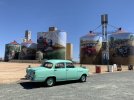
I was watching the weather and new years eve was going to be 30C with a wind of around 24kph and gusts up to 44kph so it was going to be ok to have a picnic day out in the Holden if the wind is any stronger the car is a little hard to handle on the narrow cross-ply tyres so I give those days a miss anyhow we decided to visit the town of Rushworth for the day but on the way we passed through the town of Colbinabbin which is a town with one of the many Silo Art paintings that adorn the sides of many disused railway grain silos that are all over Victoria. The silos are all that's left here the rails are long gone I remember going by train along this line just be for they ripped up the rails sometime in the 1980s the artist did a magnificent job of the painting depicting a R Class loco with a rake of GY,s behind as you can see it is painted on three curved surfaces but the train is in perfect shape no matter which angle you look at it, these Silo's are not very tall most around Victoria are 30 Meters or 100 feet high some with paintings all the way to the top of them.
David.
IMG_1900 2.jpeg
 
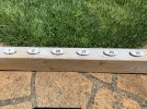
ENAMEL NUMBER PLATES

David Waite

Western Thunderer
I know this doesn't look like track work being built but I have a excuse,
Each year at the start of summer I put two sheets of sarking between the Venetian blind and the glass on each of the four Velux attic windows
to help stop the Aussie heat from melting everything inside, naturally the windows are on a angle and to put up the sarking is quite a effort so its staying there until summer is over, so the problem is I need natural light I just cannot see clearly enough by the Fluorescent lights to do any track work in the attic so I've been in the shed finishing off jobs to clear the floor space so I can un bolt the lift up sections and take them down into the shed to do the track work well that's the plan.

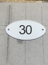
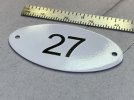
What am I up to, well the six Sykes Signal Arm Repeaters need identifying enamel number plates to show which signal they are repeating
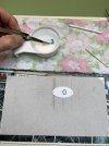
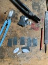
so I made a template out of paper as close to the original shape that was used and to a scale that matches the repeaters I made.

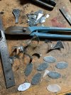
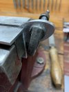
Out of various odd shaped scrap pieces of galvanised iron I cut out pieces that were large enough to cut out the oval shapes.
IMG_9567.jpeg


I cut out one and then used it to scribe the rest.
IMG_9570.jpeg


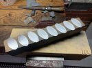
I cut out a total of eight.
IMG_9572.jpeg


All clamped together and filed as one.
IMG_9600.jpeg


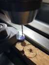
The hole being drilled will suit some small brass wood screws I have.
IMG_9606.jpeg


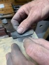
Each one was sanded smooth.
IMG_9616.jpeg


Two more than I need but will be used for future projects I have in mind.
IMG_9619.jpeg
 

David Waite

Western Thunderer
A etch primer was applied followed by a White top coat.
IMG_0594 2.jpeg


What a frustrating challenge this was the decals were like a Wrigley snake that wanted to stick to its self I ruined two in the process.
IMG_0688 2.jpeg


I won
IMG_0690 2.jpeg


They are 42.5mm x 22mm at their widest points.
IMG_0698 2.jpeg


All done with a clear coat finish, the timber that the Repeater Instruments are mounted on isn't wide enough to allow these Number Plates to be fitted underneath so a extra piece of timber will need to be machined up and attached for the Number Plates to be screwed to.
IMG_1959.jpeg
 
TYERS , SIGNAL ARM REPEATER INSTRUMENTS

David Waite

Western Thunderer
My modelling has come to a abrupt halt my good wife wants me to finish the front fence so I am in the process of painting pickets lots and lots of them and once they are all done I have to put them on so I have no time to put aside for my modelling interests therefore I thought I will start the story of my TYERS instruments that I have mentioned from time to time.

Positioned on the two timber shelves that I made directly above the RE THOMPSON repeater [ see post 166 ] there will be two TYERS signal arm repeaters these will be made to full size.
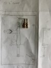
After scaling up many photos that I collected I drew a scale plan on paper that I used as my blue print.
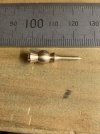
First I made the two Finials there seems to be many different shapes of these on the various instruments made over time so I chose the shape I liked the best.
IMG_1881.jpeg


Turning the Sphere.
IMG_1882.jpeg


IMG_1884.jpeg


Turning a spigot before parting off.
IMG_1888.jpeg


IMG_1893.jpeg


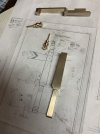
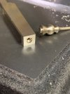
Both finished and resting on the full size plan most of the measurements are on other pieces of paper accompanied by some small drawings.
IMG_1899.jpeg


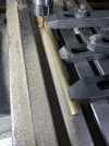
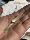
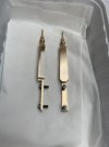
Next to be made were the two brass signal posts, the only brass I had happened to be round so it needed to be made square.
IMG_1912.jpeg


IMG_1916.jpeg
 

David Waite

Western Thunderer
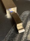
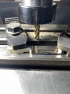
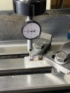
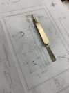
The square length I machined up gave me two pieces, the lower end of each piece was machined first this is where all
the measurements were taken from.
IMG_1927.jpeg


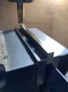
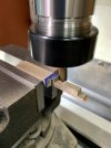
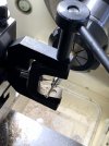
A small radius was cut across the lower end. The block between the two cuts will be machined off at the end
as it is used for a clamping support.
IMG_1929.jpeg


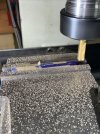
Tapered sides were machined along the lower section.
IMG_1932.jpeg


IMG_1934.jpeg


The two radiuses being cut for the start of the upper section.
IMG_1938.jpeg


The sides of the upper section are also tapered these are being machined here.
IMG_1942.jpeg


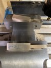
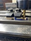
The rear of the upper section being cut out, as can be seen that block I left is being used as a support under the L/H clamp.
IMG_1960.jpeg


The rear all cut out including the machining of the two angle cuts under the R/H clamp
IMG_1965.jpeg


IMG_1967.jpeg


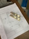
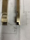
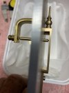
The first post in its final shape.
IMG_1970.jpeg
 

michael mott

Western Thunderer
I find it very interesting how we tackle making various shapes, from the solid, as you have done, to casting and assembling from components.
Lovely work David.
Any chance of some overall pics of your ball turning tool?
Michael
 

David Waite

Western Thunderer
Hi Michael
Here are two photos of the tool I had in my computer I can get more if you wish me to.
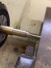
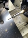
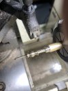
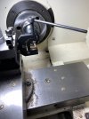
I didn't bother to make this tool even though its a rather simple item because by the time I purchased the steel and made it up it was far easer to buy one, it also came with a couple of cutting bits. The handle can screw into a few positions to keep ones hands well clear of the chuck,
in this photo the tool bit is of a stumpy grind that I used to obtain a ruff shape.
IMG_1894.jpeg


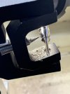
In this photo I have changed the bit, I ground another bit to a long point this allowed me to turn the Sphere far closer inwards without hitting the previous turnings either side of it, even though the cutting bit is a sharp point it turned the brass with little effort and a great finish.
This type of tool would be perfect for turning Steam domes ect as the radius can be changed simply by moving the bit inwards or out which is held in place with a grub screw, then moving the cross slide to suit. It's one of those tools that sits in the draw and doesn't get used much but when it is needed it is greatly appreciated and so much fun to use.
IMG_1883.jpeg
 

David Waite

Western Thunderer
Next job was to centre the post for the drilling of the various holes which was a bit tricky when the sides
have different tapers at each end.
IMG_2043.jpeg


The two centre punch marks were to tighten the Finial in the hole so it didn't move while soft soldering it in position.
There are two holes in the end of the post at this end the other hole is a tapped hole that actualy broke through the hole for
the finial from the underside this is for a screw to hold the top of the post against the face plate.
IMG_2048.jpeg


IMG_2073.jpeg


IMG_2066.jpeg


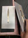
Two pieces of Aluminium were cut to size and drilled to suit the mounting screws of the posts.
IMG_2176.jpeg


The rear bearing bracket and main shaft were made up and fitted in position.
IMG_2275.jpeg


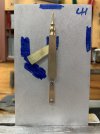
A Signal arm was made from .015"brass then,,,, this next stage I really enjoyed doing I will explain, You will notice there are 3 positions
for the Signal Arm marked on the blue Texta the position that the Signal arm is showing in this photo is the Fail safe position
that will point to the word [ WRONG ], for the arm to always rise or fall to this position from either the ON or OFF positions the Brass Signal Arm has to be perfectly balanced so the failsafe position is only obtained by the weight of the Armature on the main shaft.
IMG_2427.jpeg


To balance the Signal Arm I fitted a Bob weight to the main shaft and filed tiny amounts off it until a perfect balance was obtained.
The arm was then placed into the fail safe position and the shaft drilled to take the Armature in a vertical downwards position then
silvered to the shaft, from this point onwards gravity is now in control of the Signal arm and will always point it to the position marked
WRONG on the face plate.
IMG_2428.jpeg


IMG_2431.jpeg
 
Top