You are using an out of date browser. It may not display this or other websites correctly.
You should upgrade or use an alternative browser.
You should upgrade or use an alternative browser.
Scattergun 3.5” King Arthur ‘Sir Sagramore’
- Thread starter Tim Watson
- Start date
Tom Insole
Western Thunderer
Are you giving out autographs for your 15mins of fame… spotted someone making a horse precession on Yesterday this evening..
Also spotted this little beauty in the background!
Also spotted this little beauty in the background!

David Waite
Western Thunderer
Beautiful work Tim It has reminded me of all the flame welding I use to do.
David.
David.
Tim Watson
Western Thunderer
8 minutes and 18 seconds, actually Tom. I will return to this when the weather warms up and the garage more hospitable.Are you giving out autographs for your 15mins of fame… spotted someone making a horse precession on Yesterday this evening..
Also spotted this little beauty in the background!
Tim
Tim Watson
Western Thunderer
Back to big stuff for a while. The original water control for the RH injector on Sir Sagramore was fiddly and deep inside the cab and not at all practical. With the new injector’s streamlined plumbing I thought a water valve towards the back of the tender would be more practical. A commercial valve has therefore been adapted to fit the water pipe below the tender tank.
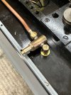
The handle was made and located with a taper pin so that it can be removed for photos. Once it is chemically blacked I don’t think it will be too conspicuous.
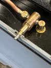
I think it should be reasonably convenient to operate. Facing forward for the ‘open’ position.
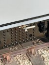
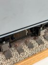
Fortuitously, the taper pin rotates against a positive stop cut into the inside of the valence - which makes positioning it much easier for ‘off’.
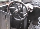
The next job will be to re-make the tender brake wheel, which currently has four spokes and it should have six.
Tim

The handle was made and located with a taper pin so that it can be removed for photos. Once it is chemically blacked I don’t think it will be too conspicuous.

I think it should be reasonably convenient to operate. Facing forward for the ‘open’ position.

Fortuitously, the taper pin rotates against a positive stop cut into the inside of the valence - which makes positioning it much easier for ‘off’.

The next job will be to re-make the tender brake wheel, which currently has four spokes and it should have six.

Tim
Last edited:
Tim Watson
Western Thunderer
The vast majority of the excellent work on Sir Sagramore was made by the late Ian Jaycroft: I am just finishing the job.
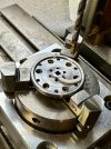
For the tender brake wheel on Sir Sagramore, a steel disc was turned up and drilled on a rotary table. A styrene spoke template can also be seen resting in the wheel face.
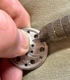
This plastic template was used to mark out the spokes using the obligatory gramophone needle.
The material between the spokes was fretted out within 40 minutes.
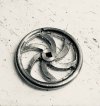
After cleaning up with files
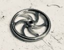
The final finishing, e.g. rounding the spokes used steel burs, stones and a rotary steel brush.
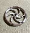
Here it is In-situ. Awaiting a knob and a steel 10BA nut. Ian Jaycroft’s gear drive to the brakes is beautifully engineered, with two quite large bevel gears. It could be made smaller with a gear set from a contra-angle dental hand-piece: but there are other more pressing things to be getting on with…
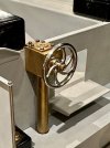
Tomorrow’s job will be to make the spinning knob for the handle.
Tim
For the tender brake wheel on Sir Sagramore, a steel disc was turned up and drilled on a rotary table. A styrene spoke template can also be seen resting in the wheel face.

This plastic template was used to mark out the spokes using the obligatory gramophone needle.

The material between the spokes was fretted out within 40 minutes.

After cleaning up with files

The final finishing, e.g. rounding the spokes used steel burs, stones and a rotary steel brush.

Here it is In-situ. Awaiting a knob and a steel 10BA nut. Ian Jaycroft’s gear drive to the brakes is beautifully engineered, with two quite large bevel gears. It could be made smaller with a gear set from a contra-angle dental hand-piece: but there are other more pressing things to be getting on with…

Tomorrow’s job will be to make the spinning knob for the handle.
Tim
michael mott
Western Thunderer
Very nice Tim did you file the square hole or use a broach?
Michael
Michael
Tim Watson
Western Thunderer
The hole was cut with a file, Michael.
Tim
Tim
Tim Watson
Western Thunderer
michael mott
Western Thunderer
Hi Tim the wheel looks to be about 1 1/2 inches in diameter beautiful work with the files. Could you share what file sizes you’re using. I have some #4 and #8 needle files my square one is a #4
Regards Michael
Regards Michael
Tim Watson
Western Thunderer
The wheel is about 30mm diameter, Michael. The hole was mainly filed up with the file below which is triangular in shape and about a No. 2 cut. It was one of several I picked up years ago and had never used. I believe they may be for a powered application, but maybe not, as this one broke into three pieces half way through the operation! Subsequently held in a pin vice, it worked well and being triangular in shape it cut sharply into the corners from the original pilot hole.
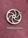
Final finishing was with a No. 4 cut two-sided square escapement file sitting on ‘17’. Another of the ‘unknown’ files is on ‘16’.
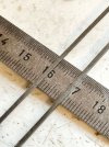
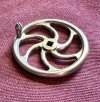
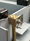
Just for comparison, this is the original wheel.
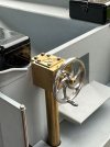
And it’s replacement
When I get back to work after Easter, I will give some slow speed dental hand pieces a serious looking at…
Tim

Final finishing was with a No. 4 cut two-sided square escapement file sitting on ‘17’. Another of the ‘unknown’ files is on ‘16’.

Just for comparison, this is the original wheel.

And it’s replacement

When I get back to work after Easter, I will give some slow speed dental hand pieces a serious looking at…
Tim
michael mott
Western Thunderer
Thank you Tim for the detailed information, I must look into some of the watch and clockmaking files.
Michael
Michael
Brian McKenzie
Western Thunderer
I will give some slow speed dental hand pieces a serious looking at…
Tim,
I asked my dentist about right-angle drive gears used in hand pieces, and he gave me this item removed from today's modern equipment - which he needs to replace every so often. I was not expecting a pressed steel like contrate, but obviously they wear doing fantastic service.
Did or do any slow speed drives use bevel gears, and could you suggest where illustrations might be found?
Dremel's right-angle drive accessory #575 uses very robust looking gears, possibly ideal for Gauge1 applications - and perhaps your brake stand if they are not too large.
-Brian McK.
Tim Watson
Western Thunderer
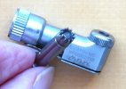
Easter came early with the revised brake wheel drive modifications for Sir Sagramore as I remembered that there was an old dental hand piece in the big workshop. After a bit of dismemberment it looked very promising:
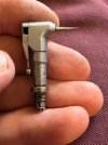
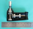
The original brake column was modified to take the hand piece head.
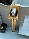
The vertical brake shaft needed splicing onto the hand piece drive, (not a trivial exercise) and the brake handle shaft re-engineered to mimic a dental bur, with a ‘latch grip’ drive. The original box, made by Ian Jaycroft, was significantly re-modelled to be closer to prototype.
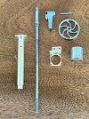
The mechanism works well, as the original alignment of the contrate gears is maintained.
The prototype has a rounded top to the brake column and this now correct on the model.
The video probably shows the quite complex arrangements better than photos.
The whole assembly is held together with 10 bolts.
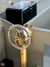
The support column should be square / rectangular in section, so that can be modified quite easily with some brass channel section.
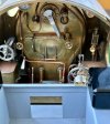
The improvement in the view from the tender I think makes all the work worthwhile.
Tim

The original brake column was modified to take the hand piece head.

The vertical brake shaft needed splicing onto the hand piece drive, (not a trivial exercise) and the brake handle shaft re-engineered to mimic a dental bur, with a ‘latch grip’ drive. The original box, made by Ian Jaycroft, was significantly re-modelled to be closer to prototype.

The mechanism works well, as the original alignment of the contrate gears is maintained.
The video probably shows the quite complex arrangements better than photos.

The support column should be square / rectangular in section, so that can be modified quite easily with some brass channel section.
The improvement in the view from the tender I think makes all the work worthwhile.

Tim
Mike Garwood
Western Thunderer
Stunning work!
Mike
Mike
Tim Watson
Western Thunderer
I’ll ask the chaps in the hospital workshop about hand piece gear types when I get back after Easter. The Dremel gears look as if they are designed to take a load in one direction only.Tim,
I asked my dentist about right-angle drive gears used in hand pieces, and he gave me this item removed from today's modern equipment - which he needs to replace every so often. I was not expecting a pressed steel like contrate, but obviously they wear doing fantastic service.
Did or do any slow speed drives use bevel gears, and could you suggest where illustrations might be found?
Dremel's right-angle drive accessory #575 uses very robust looking gears, possibly ideal for Gauge1 applications - and perhaps your brake stand if they are not too large.
-Brian McK.
Tim
Tim Watson
Western Thunderer
Just looking on ebay I found these for anyone interested.
www.ebay.co.uk/itm/203680871226?_trkparms=amclksrc%3DITM%26aid%3D1110006%26algo%3DHOMESPLICE.SIM%26ao%3D1%26asc%3D20221018081743%26meid%3D1e7a64362abd46ccbccc05155fcd288c%26pid%3D101429%26rk%3D5%26rkt%3D12%26sd%3D272894791506%26itm%3D203680871226%26pmt%3D1%26noa%3D0%26pg%3D2332490%26algv%3DSimplAMLv9PairwiseUnbiasedWebCpr08MlcBERTGreedyV3KnnRecallV1%26brand%3DSKYSEA&_trksid=p2332490.c101429.m2460&amdata=cksum%3A2036808712261e7a64362abd46ccbccc05155fcd288c%7Cenc%3AAQAHAAABIFVAfz4vmJboe8N%252FfRYfRpkGnGuVpKoiKJ1XR%252FPBbEk2IyDS9eHJSGUt14M5EGunOBPNQImpe2ExIwtTF9FZzcfPHYA1ybIYWNhPJ%252B8EnUQNR435oQWLE%252FfbYE47Tsu0QhueXMsrxQ8YqnfSlzb%252BmFV7semTN8HoqAZJIiJ2ZpaucQ%252BOzd3CA2LBvUpC2z6xWLLC2pbzm7OAHxPk6xfUGi36lDF4hBlL4yvORFf9Uo6K%252BVF0smU1nQwfKEn5rWwcs89r99OagfKAX3hAO%252Bz2ufrU65QS255gXgBe6VRi55MMQlq90PiN0nhSc3X4OKnOJK8CHTNxV17vFMElsGOK9KDq%252B3IEvVRZxi%252FtwQuhsWBCNOq0HgkFkPf9VnxeirVwyw%253D%253D%7Campid%3APL_CLK%7Cclp%3A2332490
Effectively a Chinese copy of a Japanese copy of an original German design.
Tim
Tim Watson
Western Thunderer
After a fairly heavy couple of months making 2mm scale tube railways I thought a change of size was needed. Some remedial work was needed on the cab side sheets following a mishap.
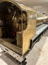
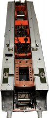
Sir Sagramore has now been dismantled to fit the ashpan and grate.
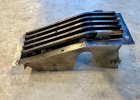
There has been a huge amount of head scratching to work out how it all dismantles and fits. Obviously, the boiler came off, but so also did the smokebox, steam pipes, mechanical oiler and reversing linkage.
The ashpan is complicated by straddling the back axle
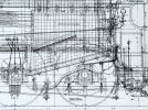
It is also complicated by having two dampers and a bottom emptying flap on the model.
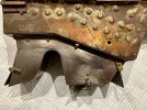
Once in situ everything gets very crowded, in this view the dampers and flap are closed.
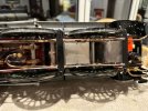
Here we see the bottom flap and front damper open.
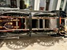
The bottom flap will be good for emptying ash and manoeuvring the grate into the firebox - for sure it will need a special tool made for the job. The front and rear dampers will also need robust linkages to work well. These will need to be threaded in to the space behind the wheels, brakes and axle driven mechanical pump plumbing. That is not too difficult, the challenge is how to bring the control linkage into the cab and also make it dismount-able for servicing and repairs.
Oh well, at least it gives the little grey cells something to think about…
Tim

Sir Sagramore has now been dismantled to fit the ashpan and grate.

There has been a huge amount of head scratching to work out how it all dismantles and fits. Obviously, the boiler came off, but so also did the smokebox, steam pipes, mechanical oiler and reversing linkage.

The ashpan is complicated by straddling the back axle

It is also complicated by having two dampers and a bottom emptying flap on the model.

Once in situ everything gets very crowded, in this view the dampers and flap are closed.

Here we see the bottom flap and front damper open.

The bottom flap will be good for emptying ash and manoeuvring the grate into the firebox - for sure it will need a special tool made for the job. The front and rear dampers will also need robust linkages to work well. These will need to be threaded in to the space behind the wheels, brakes and axle driven mechanical pump plumbing. That is not too difficult, the challenge is how to bring the control linkage into the cab and also make it dismount-able for servicing and repairs.
Oh well, at least it gives the little grey cells something to think about…
Tim
Last edited:
Tim Watson
Western Thunderer
I have now worked out the mechanism to work the bottom ashpan flap. Ian Jaycocks very cleverly used a nut-bolt fixing onto the rear brake to act as a fulcrum for the first operating crank.
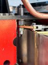
It was much easier working on Sir Sagramore with the brakes removed and this also simplified plumbing alterations.
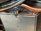
The mechanism will need a connection in the cab but I think I have a solution for that. It also gives me a steer for the damper linkages.
Tim

It was much easier working on Sir Sagramore with the brakes removed and this also simplified plumbing alterations.

The mechanism will need a connection in the cab but I think I have a solution for that. It also gives me a steer for the damper linkages.
Last edited:

