Wantage Tramway Jane No. 5 in 4mm

AdeMoore

Western Thunderer

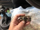
Not running great and it could be a number of things!
When I ran it as just a chassis pushed by the jinty I had to open out the bush holes in the rods to get it to run.
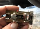
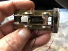
the hornblocks dont have guides as such and can twist away from vertical in their larger than expected slots.
The axles could do with cleaning up no Lubrication on the axles.
I’ll try the easy things first.


F54A922D-2297-4578-AE36-961BCDA1CCA8.jpeg
FE66A5AC-0E51-404C-9C6C-F7B8973C299A.jpeg

3595682D-F699-4A2B-8BB8-1E6991F07C76.jpeg
7B141E5A-0D13-468A-959F-909BD5EE2CCA.jpeg
2EE0A7AF-66B7-47ED-9004-9E65B03D292A.jpeg
 

AdeMoore

Western Thunderer
9BD06674-0D18-4238-A667-B7DE6D2A8511.jpeg

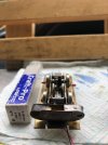
A still from the video. Looking through the holes in the frames you can see the rods are not parallel!
 
Last edited:

AdeMoore

Western Thunderer
ummm well what happened was! When I pushed the chassis with the Jinty I resorted to opening up the coupling rod bush holes to make it run!
I now realise that was not wise!
So should I shim them out with brass to the right size, scrap them and start again or something else?
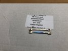
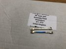
The coupling rods should set the axle centres I read but it was too late back then when I was starting out I‘d gone off the template.
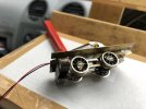
Also the nuts on the front pair I filed down for clearance came loose so they came off to see what was what.
I need to investigate the reverse crank pin set up any photos or pointers to suppliers would be welcome.
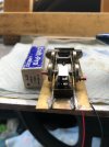
I had to put the box and label there to get the mobile to focus in the van!

8E1F277D-E272-4790-9061-A9C1DED845EB.jpeg


38C4E694-133E-44C4-A6B3-217660CBBD68.jpeg

FECCEF92-D786-4A02-99BD-CBE36CF34839.jpeg

3567B51D-0CD6-4FE6-A1E8-DBD43F452648.jpeg

Cheers for looking in.
Just a few tags for those who have helped previously!
@Dave Sutton @adrian @simond @Robin @Ian@StEnochs @Overseer thanks in advance.
 
Last edited:

John Hutnick

New Member
The best system to set the holes is a little work, and more or less needs a lathe.
Take out the drivers. Make 2 replacement axles with the ends turned to crankpin diameter.
Take(or make) your 4 crank bushings and place on these axle ends.
Make holes in the siderods big enough to easily slide over the bushings. Then solder the bushings securely in the siderods.
In theory, you are now done.
You may wish to just start over siderods using N/S scrap from etchings.
 

AdeMoore

Western Thunderer
The best system to set the holes is a little work, and more or less needs a lathe.
Take out the drivers. Make 2 replacement axles with the ends turned to crankpin diameter.
Take(or make) your 4 crank bushings and place on these axle ends.
Make holes in the siderods big enough to easily slide over the bushings. Then solder the bushings securely in the siderods.
In theory, you are now done.
You may wish to just start over siderods using N/S scrap from etchings.
Thanks for the reply John no lathe here! The most basic of basic set ups all handrolic!
Im thinking make up the original jig again.

8CC9E423-8973-41F3-8EBC-3F2E183D2791.jpeg

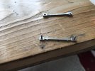
shim out the holes with brass to the pins, solder then drill out as a pair each end for the bush.
what do you think?
 

Lyndhurstman

Western Thunderer
ummm well what happened was! When I pushed the chassis with the Jinty I resorted to opening up the coupling rod bush holes to make it run!
I now realise that was not wise!
So should I shim them out with brass to the right size, scrap them and start again or something else?
The coupling rods should set the axle centres I read but it was too late back then when I was starting out I‘d gone off the template.
Also the nuts on the front pair I filed down for clearance came loose so they came off to see what was what.
I need to investigate the reverse crank pin set up any photos or pointers to suppliers would be welcome.
I had to put the box and label there to get the mobile to focus in the van!

View attachment 174273


View attachment 174272

View attachment 174275

View attachment 174274

Cheers for looking in.
Just a few tags for those who have helped previously!
@Dave Sutton @adrian @simond @Robin @Ian@StEnochs @Overseer thanks in advance.
Hello @AdeMoore
Obviously the biggest issue is getting the axle centres accurately transferred to the coupling rods. This is not easy. This is the way I did it on the Y4:
Post in thread 'Jan's 4mm Workbench'
4mm - Jan's 4mm Workbench

If you were building this from a kit, then the frames would be built up using the rods as datum, If with some alignment jigs from London Road Models or Markits
http://traders.scalefour.org/LondonRoadModels/images/alignmentjig.jpg. There is another (better) version that has parallel ends the same size as crankpin bearings, but I don’t know where you can get them. In your application, these - used in conjunction with a tapered broach - might be handy in getting the connecting rod pitch the same as that of the chassis. The broach would maintain the concentricity of the hole and prevent it becoming oval - which would introduce binding.

So really - for me - it’s whether you can find some way to rework the pitch of the holes accurately.

Failing all that, i would start again, and open out the holes in the rods incrementally with small drills, ending with a tapered broach to maintain concentricity.

Cheers

Jan
 

Dave Sutton

Active Member
ooooh difficult one. I was able to build the frames and bearings with the rods in a jig.

Have you got any overlong axles/rod? You need to check if the bearings in the frames are parallel. I'll have a look in the 'bits' box and see if I've got anything, I moved house a while ago and we're in a rental while I build our new one so it may take a bit of time to find. I'll also look to see if there are any spares left.
 

AdeMoore

Western Thunderer
Hello @AdeMoore
Obviously the biggest issue is getting the axle centres accurately transferred to the coupling rods. This is not easy. This is the way I did it on the Y4:
Post in thread 'Jan's 4mm Workbench'
4mm - Jan's 4mm Workbench

If you were building this from a kit, then the frames would be built up using the rods as datum, If with some alignment jigs from London Road Models or Markits
http://traders.scalefour.org/LondonRoadModels/images/alignmentjig.jpg. There is another (better) version that has parallel ends the same size as crankpin bearings, but I don’t know where you can get them. In your application, these - used in conjunction with a tapered broach - might be handy in getting the connecting rod pitch the same as that of the chassis. The broach would maintain the concentricity of the hole and prevent it becoming oval - which would introduce binding.

So really - for me - it’s whether you can find some way to rework the pitch of the holes accurately.

Failing all that, i would start again, and open out the holes in the rods incrementally with small drills, ending with a tapered broach to maintain concentricity.

Cheers

Jan

The paralell end ones were perseverance. I don't think theyare available any more.

Poppy's Wood Tech supply these with their Builder Boxes - in 1/8" and 3/16"

View attachment 174294

ooooh difficult one. I was able to build the frames and bearings with the rods in a jig.

Have you got any overlong axles/rod? You need to check if the bearings in the frames are parallel. I'll have a look in the 'bits' box and see if I've got anything, I moved house a while ago and we're in a rental while I build our new one so it may take a bit of time to find. I'll also look to see if there are any spares left.
Thanks for all for the replies Jan I was looking in on the Y4 thread thanks.
Paul 1 & 2 ! Thanks.
I have seen the Poppys jig before and was tempted thanks.
Dave ever kind but let’s see if I can sort it before you go putting yourself out as you always kindly do.
What I used 1/4 inch drill bits when doing the hornblocks seemed ok. I have a spare pair of rods in the band new etch you sent me If I need.
I was thinking if I get a pair of rods identical. Then I need a pair of those guides as seen in the Poppys jig above, put the rods in the chassis and solder up the hornblock guides to suit. There are none at present they just float in the chassis slots I made for them.
Seems not a good idea by eye so need a jig!
I’ll refer back to a few threads for ideas.
 
Top