Sieg SX3 Mini Lathe improvements adventure

Rob Pulham

Western Thunderer
Hi Mick,

Because I do plan to use the feed screw. It also made sense to do it all while I had it in bits for the extra time and minimal expense.

I hope that once these improvements are made that I should have to do very little to it in the future other than lubrication etc.
 

Rob Pulham

Western Thunderer
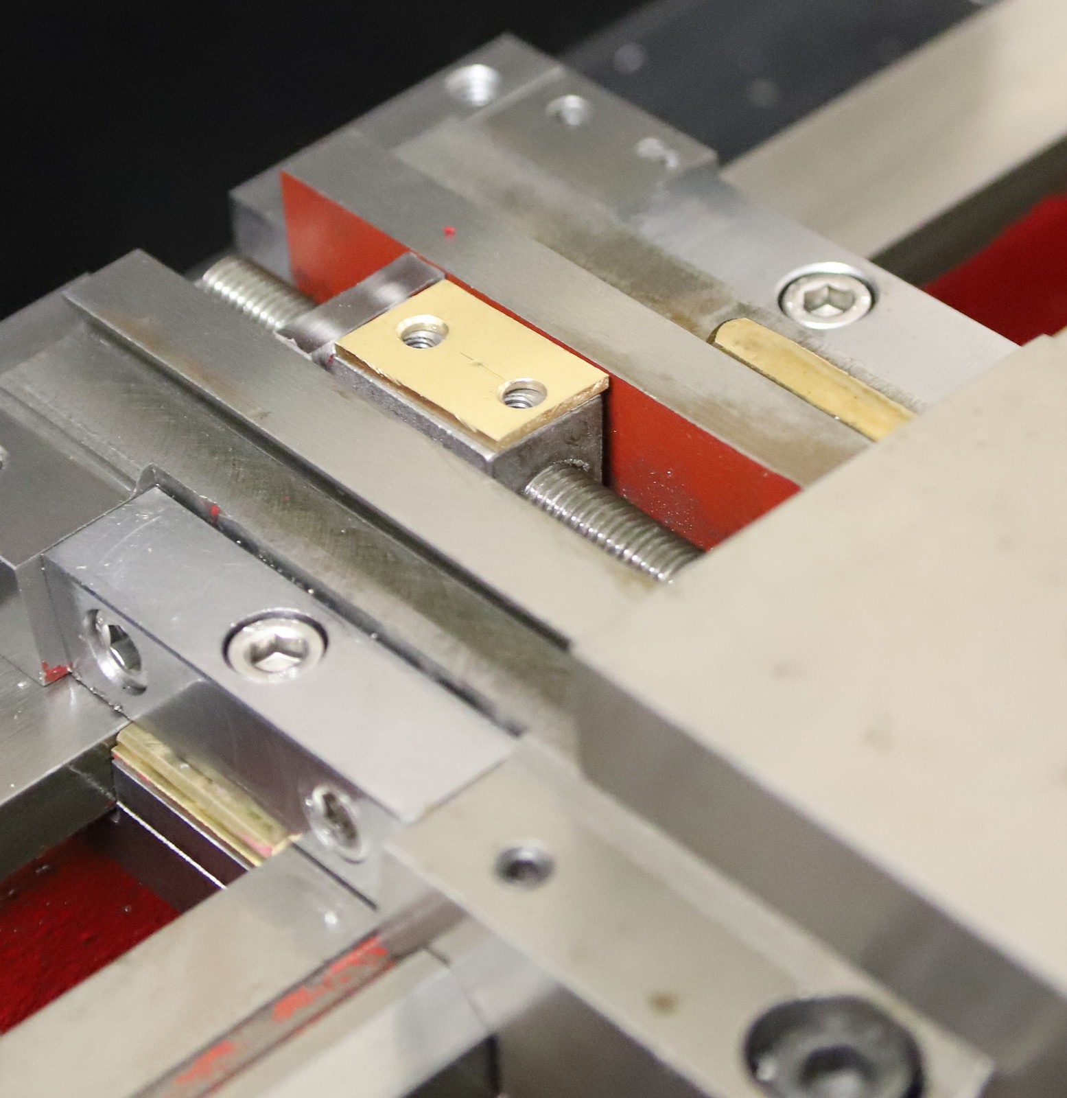
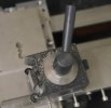
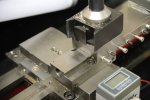
A bit of a milestone reached this evening as it's almost ready to reassemble. I just need to cut some lengths of M6 studding to fasten the bottom slide bars on with. Then once the basic carriage is reassembled and fitted on the ways, I need to mark out, drill and tap the carriage lock before reassembling the cross and compound slides.

51828978331_80abaa0837_h.jpg


51829318519_ec18e80de7_h.jpg


There wasn't a lot of depth and I wanted them countersunk to retain as much cross slide travel as i can also I doubt if these will ever get unscrewed again once finally fitted so I used M6 button headed cap screws instead of the usual deep headed type.

51828024782_dc867c3e21_h.jpg


51828976091_4e088b1fa1_h.jpg


51829330369_71a67d4828_h.jpg


This is what it will look like when all fitted together.

The end support piece and the bottom of the carriage lock are made from the same piece of bar (eBay purchase) and must be free machining as recommended by Mike Evans, because they machined, drilled and tapped so much easier than the steel that I made the other parts from.
 

Rob Pulham

Western Thunderer
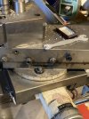
After spending most of the day trying different thicknesses of shims to get the most rigid, but sliding fit the carriage is back together. As I had hoped a 1/4 turn of the rear cap head screw locks the carriage.

I also cut a spacer/shim to fit on top of the feed nut to do away with the need for rocking about a grub screw. I have left the grub screw in place to stop the hole filling with swarf but it's no longer functional.

This is the spacer in place before attaching the cross slide.

51832593432_ed4a5b953a_h.jpg


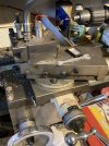
Next was reassembly of the apron, cross and compound slides ready for a test run. It all went back together nicely but getting the main lead screw cover in the right place for the power feed half nuts to engage/disengage properly was a right pain and took several adjustments before everything ran smoothly.

51833533316_3b73caf8b6_h.jpg


51833532601_0f3f1f7a23_h.jpg


I still need to make a couple more spacers/shims to take more backlash from the cross slide but I needed the lathe back together to turn them.
 

Rob Pulham

Western Thunderer
Thanks Giles,

Yesterday I had turned a spacer for the cross slide leadscrew which along with the extra backlash nut that I made earlier has removed all the backlash from the cross slide.

This morning saw the final piece in the current puzzle, the replacement for the missing compound handle. Turned from 8mm stainless, I am really pleased with how much different the lathe performs now that I have made the improvements.

51838386304_5739320bc6_h.jpg
 

OzzyO

Western Thunderer
51833532601_0f3f1f7a23_h.jpg


I still need to make a couple more spacers/shims to take more backlash from the cross slide but I needed the lathe back together to turn them.

Hello Rob,

how does your compound slide rotate and lock in an angled position?

As if it just lives in that position it's going to be a bit of a problem using the nice carriage lock that you have just put in place.

I'll have to have a look at my late to see how things are arranged on that and pop a photo or two up.

ATB

OzzyO.
 

Rob Pulham

Western Thunderer
Hello Rob,

how does your compound slide rotate and lock in an angled position?

As if it just lives in that position it's going to be a bit of a problem using the nice carriage lock that you have just put in place.

I'll have to have a look at my late to see how things are arranged on that and pop a photo or two up.

ATB

OzzyO.
Hi Paul,
That's another thing that I may alter if it becomes a pain. To get access to the cap screws that allow rotation of the compound slide, you have to wind the compound slide back quite a long way.
I will take a photo to show what I mean.
 

adrian

Flying Squad
First of I must say none of these mods I've done. These were fitted by the previous owner but I'm glad he did do them.

The carriage lock is a slightly different design in that it bolted to the top of the carriage however I've included it to show the locking mechanism and it might give a few hints on operation for yours.

It's sprung loaded cap on top of the locking bolt with a nice little fitted tommy bar. This is the unlocked position.

lathe - 1.jpeg

This is the locked position. So it's easy and quick to reach and lock even if the top slide is over the top of the carriage lock.

lathe - 2.jpeg

The second mod is regarding your comment about having to wind back the top slide a long way to get to the locking bolts. If you compare this one to yours you can see the base of the top slide is mounted further back on the cross slide. The previous owner had obviously got fed up of winding the top slide so far back that he drilled 2 new holes further forward and mounted the top slide further back.

lathe - 3.jpeg
 

Rob Pulham

Western Thunderer
Thanks Adrian,

I do like the look of the carriage lock.

With the compound slide, has having it mounted so far back affected the rigidity? That would be my biggest concern especially after the effort that I have put in to make it more rigid.

I have seen multiple ways of dealing with the issue from simply drilling two holes through the compound slide itself to get at the screws, to some fairly complex cutting of the sides with slitting saws to enable nuts to be used on studs and even a replacement for the turntable with a dovetail tapered pin in the middle but I haven't seen anyone do it as yours is done.

For those who have no idea of what we are talking about. To rotate the compound slide to turn tapers at the minute, I have to wind the compound slide so far back that another half turn see it disengage from the leadscrew.
IMG_0586.JPG

IMG_0585.JPG
 

OzzyO

Western Thunderer
Hello Rob,

this is what I was trying to put across, how do you set you top slide to an angle? Or is it more like a fine feed for the longditudinal travel?
This is how my top feed is mounted, it's set at 20 degrees at the moment, the only problem I have with it is if I want to set it to an angle in the other direction as the swarth guard can get in the way.
IMG_4049.JPGIMG_4050.JPGIMG_4051.JPG

ATB

OzzyO.

PS
do you have a photo of the top slide without the compound slide in place?
 
Last edited:

Rob Pulham

Western Thunderer
Hi Paul,

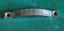
Originally it would have had a rather crude cast aluminium protractor fitted to the front of the slide like yours but it's missing from mine.

Oddly I don't seem to be able get one as a spare, despite virtually every other part being available as spares.

In lieu of having one fitted I have bought stainless steel protractor that I use when setting important angles. - not the same but very similar to this one but admittedly not quite as nicely finished off (image linked to from a random website and copyright of them) Mine came from eBay and was only £2.99 inc postage

gradmesser-310356a.jpg
 

Stephen Freeman

Western Thunderer
The one I have is a Conquest, which seems similar if not quite identical, The method of rotating the topslide does seem awkward compared to an ML7 though. The mods look like they could benefit the Conquest as well, though I still look upon the ML7 as the goto machine, as long as it doesn't get too cold, I can always bring the Conquest into the house if needs be.
 

GrahamMc

Western Thunderer
how do you set you top slide to an angle?
slide.png

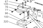
Part 100 is the cross slide with the hole, part 96 the bit that rotates within the hole and the compound slide base (105) bolts to part 96. The bolts (67) are loosened to allow rotation. It's getting to the bolts is a fiddle as they're under the compound slide.
 

OzzyO

Western Thunderer
View attachment 155512

Part 100 is the cross slide with the hole, part 96 the bit that rotates within the hole and the compound slide base (105) bolts to part 96. The bolts (67) are loosened to allow rotation. It's getting to the bolts is a fiddle as they're under the compound slide.

Thanks for that Graham, it has all become clear now. It looks to be a bit of a parp to set up but should be nice and solid when set up.

ATB

OzzyO.
 

Stephen Freeman

Western Thunderer
Clearly there are also a couple of bits missing off mine, but as it didn't cost me anything (other than to source suitable switchgear) I can't complain. The Conquest seems to be similar to the C3 mentioned, so perhaps the carriage lock will be easier.
 
Last edited:

adrian

Flying Squad
Oddly I don't seem to be able get one as a spare, despite virtually every other part being available as spares.

Mine is redundant with the top slide moved back as it no longer lines up on the pivot point. So you are welcome to have it if required, although as you can see from the graduations any angle is indicative only.

lathe - 1.jpeg
 
Top