Hi Martin
It‘s such a history lesson reading your thread thank you.
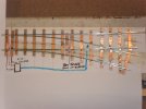
With the flexing of the switch blades braking the solder joints and to keep the points looking as they should with no noticeable alterations would it be worth pivoting the two fixed blades by removing the solder at positions marked with a Blue X and making the two fixed switch blades pivot at the position shown in red on the photo below by using a 12 ba screw or a piece of rod or similar through from the underside of the sleeper into the rail and (if needed closing the gap a little by bending the rail shown in Black so when the diverge position is set the check gap is correct).
David.
View attachment 213705
Hi David
Thank you for your comments and suggestion.
Your idea would certainly work as it removes the need for the switchblades to flex, so there would be no strain on the soldered joints in normal operation. I had considered a similar approach based on cutting through the rails that form the switchblades near the crossing and making them into a separate pivoted assembly, as was done in the post-war scale permanent way. I might try out either, or both, these approaches in future. I am not sure they will be much easier or quicker to do than what I have done so far. Generally, the soldered joints securing the wing rails don’t break, certainly not the joints furthest from the crossing. So I have been reluctant to disturb these as they preserve the relative positions of the different running rails.
My approach to date has not been to alter the way the points operate, but to strengthen the soldered joints so (I hope) they are strong enough not to fail. Additionally, to introduce more flexibility into the connection between the tie bar and the point lever, so the switch blades are free to swing in an arc, rather than just move transversely across. The combination of reduced stresses from a more ‘natural’ flex and stronger joints should be durable, I feel. Come back to WT in 100 years time to find out!
I don’t think the original Lowko Track design is far off being OK for 3’ 2 1/4” radius points. Lowko track was also made in 2’ radius. The distance between the toe of the switch blades and the crossing is obviously far less in 2’ radius points and they are always broken. I have never seen a 2’ turnout with the soldered joints intact. (I was never going to be using such a small radius anyway, so not my problem). In 3’ 2 1/4” radius points with tinplate rails, joints at one or other end of the switchblades have usually failed. Not every time, either because the turnout has had little use or the soldered joint was particularly strong or the tinplate rail was particularly flexible. There is certainly some variation in the rails as to how ‘splayed’ the bottom webs are and this does seem to affect how easily the rails bend. Also the removal of one web from the rail to form the switchblade extends further from the toe in some points than others reflecting the hand-made construction. I have only three factory made Lowko Track points with brass rails. So, based on this very small sample, I would say soldered joints are less likely to fail with brass rails, no doubt because they bend more easily. I have never seen a factory made 4’ radius Lowko Track LH or RH turnout in 0 gauge (these were only listed pre-WW1). However, the ‘complete crossovers’ listed until production of Lowko Track ceased used two 4’ radius points. I have several of these but mostly very distressed and not repairable. It is difficult to distinguish between failed soldered joints due to flexing of the switchblades in use and the damage caused when granny stood on the crossover. My impression though is the extra length of the points in the crossovers reduces the strain on the soldered joints sufficiently for them mostly not to fail.
Based on the above, my conclusion is that a modest strengthening of the soldered joints plus some additional flexibility should be enough to allow 3’ 2 1/4” radius Lowko Track points to be used regularly and not break.

