Paul Cram's S7 thread

Paul Cram

Active Member
Having purchased a Connoisseur Models J71 kit I realised the frames as they come are too narrow for S7. Too wden the frames I needede a way of hodling them whilst fitting the wider frame spacers.

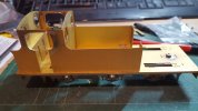
I have turned up a couple of jigs too ho;d the frames and at the same time turned up some axle jigs to set the hornblocks accurately to yje coupling rods.20231020_170316.jpg
 
Last edited by a moderator:

simond

Western Thunderer
Paul,

my dummy axles are around 125mm long, it shouldn't matter, but having them longer is likely to minimise any errors in the same way a pantograph does. If you’re making your own and you have the material, it’s an easy win.

I like your temporary frame spacers. Solid job!

atb
Simon
 

adrian

Flying Squad
Paul,

my dummy axles are around 125mm long, it shouldn't matter, but having them longer is likely to minimise any errors in the same way a pantograph does. If you’re making your own and you have the material, it’s an easy win.

I like your temporary frame spacers. Solid job!

atb
Simon
I build them up separately. I use very short stub axles to solder in the hornblocks on each frame. My thinking on this is I want the coupling rods as close as possible to the hornblocks when fixing the position. My doubts with longer dummy rods is guaranteeing that they are perfectly straight. Short stub axles less likely to deviate IMHO.
3F-chassis-1.jpeg

I then use longer rods when assembling the chassis to ensure it is straight and square - the longer rods used to indicate any twisting of the chassis and allow me to double check that the axles will be square to the chassis, hence engineers square in the photo.
3F-chassis-4.jpeg
 

mickoo

Western Thunderer
I build them up separately. I use very short stub axles to solder in the hornblocks on each frame. My thinking on this is I want the coupling rods as close as possible to the hornblocks when fixing the position. My doubts with longer dummy rods is guaranteeing that they are perfectly straight. Short stub axles less likely to deviate IMHO.
View attachment 198634

I then use longer rods when assembling the chassis to ensure it is straight and square - the longer rods used to indicate any twisting of the chassis and allow me to double check that the axles will be square to the chassis, hence engineers square in the photo.
View attachment 198633
I do much the same with the hobby holidays jig, do each side at a time with as short as possible rods.
 

Paul Cram

Active Member
Right an update on progress. Having fitted the cab floor, toolboxes and cab splashers I then the suplementary instructions again. Here I noticed that the cab interior had been revised to correct a previous mis reading of the drawin. The etched splashers have been replaced with a combined splasher and rear of tanks casting. Also there is a packing piece which fiehind the back head which requires the floor to be cut back. So unsolder the cab front tool boxes and cab floor. Trim to accommadate larger back head. I decided to keep the etched splashers so cut off the casting. They also required trimming to fit around ther edge of the backhead. Resolder floor, toolboxes and cab front. The smoke box was comstructed and the slots for locating the sides were found to be too far appart. Careful filing of the inside faces alsmoke box to correctly locate.

20231102_144300.jpgThe front splasher/sand box has been fitted on this side. Other side still to do. The tank inside etches still need soldering. I need to decide how much lead to firt in them. not sue an approriate weight is for a 7mm loco.
 
Top