Nick Dunhill's workbench - Scratchbuilding a Reid NBR Atlantic from an ACE Kit.

Nick Dunhill

Western Thunderer
Hi All
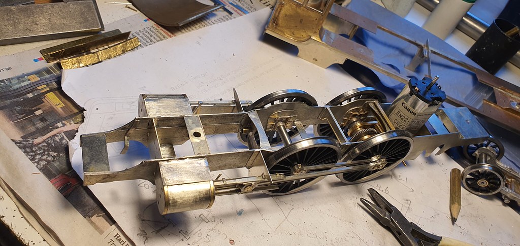
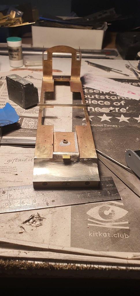
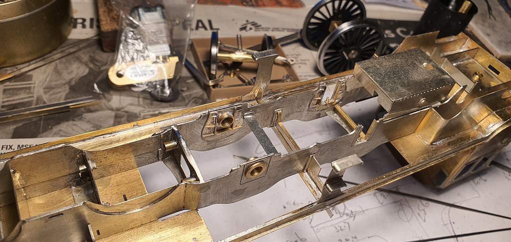
New project! It's a ACE Kit for the Reid C10 NBR Atlantic. The kit was part built by Graham Varley before his untimely death earlier this year, and we decided to finish it as a tribute to him. Graham had (very nicely, as was his way) built the footplate, cab and the main part of the tender. He'd then come across an issue or two and put the model in his dusty 'pending' pile in the hope that it would be forgotten!

The first thing I decided to do was to replace the awful front section of the footplate top. The underside of it has a half-etched rectangle to aid curving, but it had left awful witness marks in the top.

52410970436_f3f8251443_b.jpg


52411412745_d4bc96ba60_b.jpg


52410970591_bd2144d068_b.jpg


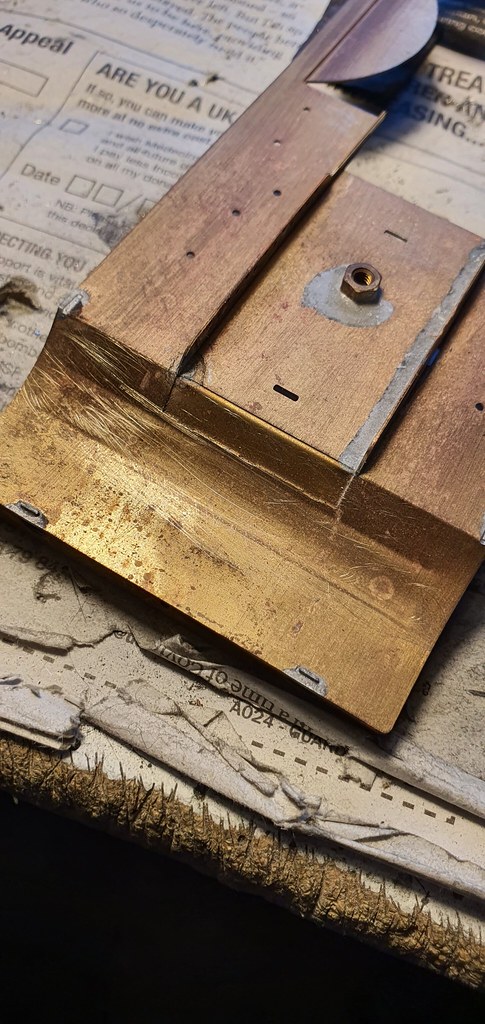
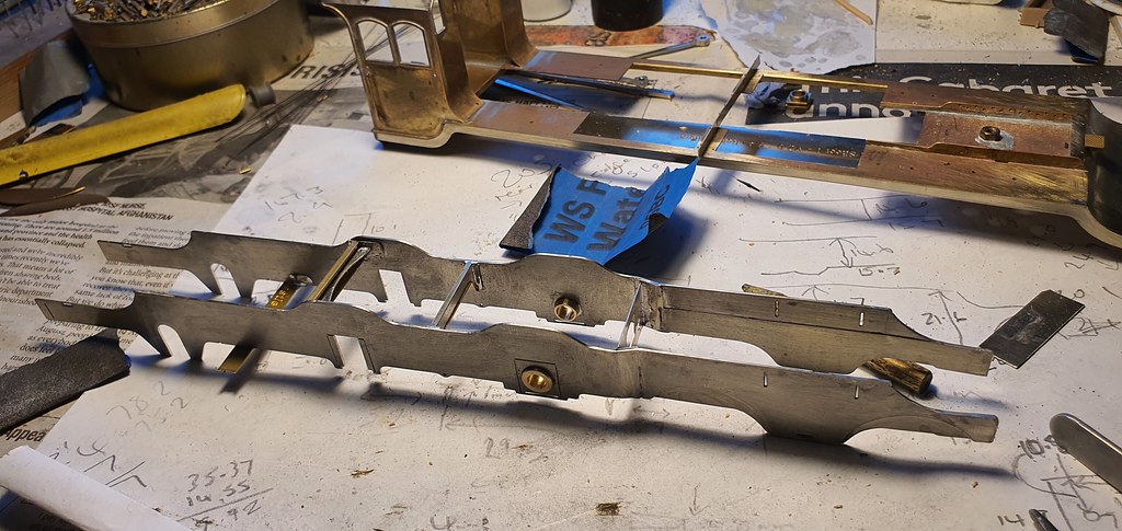
Robin McHugh is something of a guru on scottish locos and pointed out to me that the footplate valences were too shallow so....

52411318644_66fd8b5908_b.jpg


52411413410_b0cf9f99a2_b.jpg


52411318294_bbba9df860_b.jpg


52411037446_7ac856deeb_b.jpg


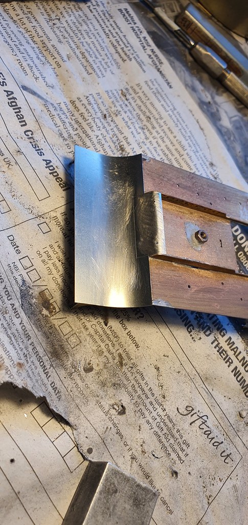
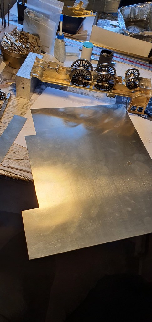
There's no easy way to do this. Measure (twice!) cut, fit. The splasher (out)sides were removed from the footplate etch as the fold line is too thin and you cant make a 90 deg fold!

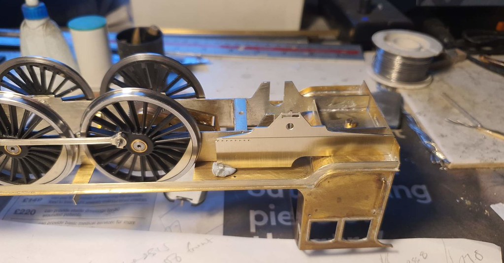
It looks much better, and I capped off the week by fixing the smokebox step.

52410564917_4dd9bb0483_b.jpg


This will be fun.
 

adrian

Flying Squad
He'd then come across an issue or two and put the model in his dusty 'pending' pile in the hope that it would be forgotten!
I have one of those piles as well - the problem is it's larger than the completed items!!
The first thing I decided to do was to replace the awful front section of the footplate top. The underside of it has a half-etched rectangle to aid curving, but it had left awful witness marks in the top.
Another pet hate of mine, I understand the kit designer is trying to be helpful but it usually causes more problems than it solves.
 

Nick Dunhill

Western Thunderer
After assembling 4 models back from paint it's back on with the Atlantic. I've been chatting a lot with Robin McHugh about this loco. He has a wealth of knowledge about these prototypes and bought himself one of these kits and I think we are now building in tandem.

This week I got the chassis etches out of the box. I noticed that the etches were intended for use in the ACE GC Jersey Lilley kit, but it turned out that the wheelbases of both locos are identical, my measure-o-meter (I've taken to measuring everything with this kit) confirmed that the wheels would all be in the right place in relation to each other. However the frames only fit to the footplate where they touch....that is at either end. More pondering over the drawing revealed that if the front of the frames are up against the rear of the front buffer beam, by luck or design, the wheels (and maybe the cylinders, we live in hope) fall into the correct position. Turns out that the rear driving axle falls in the centre of the rear splasher apperture on the footplate. The front driving axle is about 1.5 mm ahead of the splasher apperture, so we'll have to modify that later.

52460060747_ec6d9cd9a7_b.jpg


I held the frame under the footplate and used drill shanks as feeler gauges to determine that the gap between the tops of the chassis and the underside of the footplate was 1.1 mm. I scratched my head deciding whether to cut my losses and cut out new frames or modify the etches. I decided to modify, and it probably took nearly as long as cutting out new items. The frames are joggled between the front driving axle and cylinder block and taper in between the front of the cylinder and buffer beam, I put all of the bends into the chassis frames. The frames on the real loco aren't scaloped to give clearance for the bogie wheels. I infilled the fronts of the frames and keep my fingers crossed that there'll be enough clearance for the wheels not to hit the frames on a 6' rad curve.

52460060577_22a3733a87_b.jpg


The manufacturer just supplying a random chassis caused a lot of extra work. The chassis needing so much modification is not really acceptable.

I decided to make the frames 27-odd mm apart to give clearance for the inside motion. My measurements show that a Slater's SG29 motor and gearbox will fit between the eccentric sheaves. Of course none of the frame stays now fit and I so far have scratchbuilt the stay that supports the rear end of the valve rods, the one between the drivers and the one in front of the firebox.

52460581081_3166aa5ce1_b.jpg


52461028930_17e400c18e_b.jpg


52461113018_bf4dcb6752_b.jpg


I sense a lot of mission creep...
 

Nick Dunhill

Western Thunderer
So the first jobs this week were to finish the frame stays and install the valve rods. All went well...

52474182697_84c49785f1_b.jpg
[/url]

The cast valve rods are part of a LGM inside Stephenson motion set that will feature later in the build.

The next logical step would be to pop the wheels in. I normally trust the kit design, but in this case I mocked up the rigid axle in the chassis and placed the footplate and cab on it. For piece of mind I levelled the footplate (with a block of wood and some shims) with everything sitting on the one fixed axle. The whole footplate sat about 1.1 mm too low! The front buffer beam has the holes for the buffers offset (the buffers should be central in the buffer beam,) and this could well be the solution to bring the buffers up to the correct height above rail with the whole body sitting too low.

52475228428_89c9123f67_b.jpg


Well that's one solution to the problem. The other of course is to move the bearings in the chassis frames, which is the solution I chose. I refer to my comments above about whether to modify the frames or make new!

I put the driving wheels in the chassis and finished the frame stays and a motor mount. The motor is a Slater's SG29.

52475147500_6188aaa941_b.jpg


The next job was the outer frames round the rear axle.

52475289528_d1c2f43e21_b.jpg


52475146315_9790ef3b44_b.jpg


52475228433_7ee20eb9b8_b.jpg


52474961819_8a0dd6c6e3_b.jpg


For the record there was nothing in the kit to locate the rear wheel set, so I had to fabricate a basic pony style truck.

Tomorrow I will look at the cylinders. Place your bets on whether they will fit!
 

Nick Dunhill

Western Thunderer
I tried turning my attention to the cylinders, but I fell down a different (deep) rabbit hole. I made some dummy hornguides, nothing too elaborate so they didn't skim much off the budget. I put another frame stay in place too that I had overlooked when staring at the GA.

52491127735_0ce84556a2_b.jpg


You can see that I also fabricated an ashpan. The ashpan sides in the kit required a little modification but nothing that made my scrap bin much heavier. I decided that it would be sensible at this stage to also make the footplate support bracket that is between the driving wheels. It is also a support bracket for the steps that are also between the driving wheels, and is cut in a way that doesn't bring it into conflict with the coupling and connecting rods. I searched through the etchings in the box for the step parts. There were treads (wrong size) for the cab and tender steps but nothing for the massive, conspicuous steps between the driving wheels. So a bit of measuring and cutting later and..

52491127595_e2e52b752e_b.jpg


52491127735_0ce84556a2_b.jpg


Eventually I got to the cylinders, and they required some new ones to be made. I also had to scratchbuild slide bars and crossheads too. The slide bar etches on the 'kit' were too short by a mile (they were maybe correct for a Jersey Lilley) and there's virtually nothing in the box for the crossheads.

52490941534_fa6758b26d_b.jpg


This pic shows one of the basic carcasses for the cylinder block. The front and rear were salvaged from the kit etches, the pile of strips is what I sorted through to find suitable material for the slide bars. Always save the waste strips from kit etches kids!

52491128905_86950a5db2_b.jpg


The main story of this photograph is that the centres of the connecting rods are wrong. I chopped a big hole in the small end, made a jig and soldered the small end bearing in the correct place. In this way I can position the cylinder block correctly on the chassis side.

Here are the nearly complete cylinders. The crossheads are bloody awkward things to make and some castings really would have helped. How the budget for this job shrinks!

52491128935_44223c0994_b.jpg


I'm getting through a lot of piercing saw blades, but hopefully I can finish the cylinders tomorrow and make the front bogie.
 

michael mott

Western Thunderer
Nick I am thinking that all my little hiccups while scratch building are at least my own errors and not the work of someone else, I can sense your frustration with so much correction being needed.
Michael
 

Nick Dunhill

Western Thunderer
Misrepresentation is the legal phrase I think Col.

Having completed the cylinders this is how I fitted them up onto the chassis. It's important that the centre line of the cylinders crosses the centre of the driven axle. You can see that I put a rod down the tube that carries the piston rod and lined it up with the wheel centre. To achieve this I soldered some packing pieces onto the top of the cylinder front to achieve the correct position according to the GA. I then shoved successive diameter drill shanks on top of the cylinder rear until the correct incline was achieved.

52493602212_f5f2f036a8_b.jpg


52493602162_2f79861238_b.jpg


BUT I also checked the fore and aft position of the cylinder by installing the con rod and moving the wheel such that the piston would be a top and bottom dead centre, iin this way I can move the cylinder until the crosshead falls into the correct positions on the slide bars.

52494367829_a6a3402744_b.jpg


52493602152_39137f8069_b.jpg


This is an iterative process and you have to hope that the cylinder falls into the centre of the bogie. Fingers crossed.

The cylinders are only tacked for now so can be corrected later if needed when the bogie is offered up.

Finally here's a rendition of some printy axles and springs I commissioned to replace the ghastly castings in the kit.

52491214308_c0eaea920e_b.jpg


Thanks to Mick Davies.

More struggles with the brake rigging next week.
 
Last edited:

Nick Dunhill

Western Thunderer
From a past experience (I made a Hush-Hush from an ACE Kit a decade or two ago) I kind of expected it. I'm been paid an hourly rate for all the work so I'm sort of enjoying a bit of gratuitous scratchbuilding. On the other hand I can't submit an invoice equal to the cost of Brexit, so I have to be mindful not to get carried away.
 

Nick Dunhill

Western Thunderer
Continuing from last week, after both cylinders had been fitted I made the muck shields that back both slide bars. They are huge and cover the whole of the backs of the slidebar area. After that I made some motion brackets, there were random shaped etchings in the kit for these items that now reside in my scrap bin.

52506527954_dbe62a33a8_b.jpg


As you can see I also did the final fit-up of the rods. I had to make a pair of spacers that fitted between the coupling and connecting rods, over the crank pin. This was to move the con rod big end outwards so that the rod is parallel to the slide bars and frames. This is often overlooked in kit builds, but the prototype con rod was definitely not angled, disaster would quickly follow.

The next logical item to make was the front bogie and equalising beams. There were random etchings in the kit for these items that now reside in my scrap bin. Laurie Griffin does a Drummond bogie side frame kit, and it is almost identical to the one on this loco. I wonder if the etches supplied are even for a Jersey Lilley? I made the bogie stretchers from lengths of U-section soldered together, the bogie has rudimentary side control. I had to make some guard irons for the above, there were random shaped etchings in the kit for these items that now reside in my scrap bin.

52506527584_e22ab0f6d6_b.jpg


The rolling chassis was now complete and to my relief went round a 6ft curve.

52506255861_6f02e27d94_b.jpg


I added some bits of brass strip that limit the movement of the front of the bogie to prevent shorting, as the front of the frame is not scalloped above the wheels.

52506255806_ce25bba78c_b.jpg


The next step this week was the inside motion, there's nothing usable in the kit for this, and I began by fitting the eccentric sheaves. These need to be removable as they share an axle with the gearbox. I had loads of sheaves CNCd in steel to replace the castings in LGM inside motion sets a while ago, they save loads of fettling. (I have loads so if anyone wants a set at cost let me know.) The axle holes were opened up and they were soldered to short lengths of brass tube that telescope over the axle. The axles and tubes are drilled to accept a steel driving/locating pin.

52506808558_4a79e548fd_b.jpg


The pin will stop the eccentric straps falling off.

52506527179_4fae568488_b.jpg


The week ended with the fettling of castings for the eccentric straps and forked-ends. The rod itself has to be scratchbuilt as they are quite long and shaped to avoid the front driving axle. The cast rods in the LGM set were too short.

52506527144_476d1f1277_b.jpg


My scrap bin is getting quite full. The cat is there for scale.

52506801310_408f4d78c5_b.jpg
 

Overseer

Western Thunderer
My scrap bin is getting quite full. The cat is there for scale.
Clever cat being able to weigh scrap metal. :)

More seriously, if you keep the nickel silver separate it can be melted for lost wax casting, as can the brass but that is more readily available.

A lovely model is appearing from your tribulations.
 

Nick Dunhill

Western Thunderer
You know what Fraser I spent ages a few years ago carefully separating the brass from the nickel silver. When I went to the local scrap merchants they weighed it and tipped it all into the same bin!
 
Top