7mm Mickoo's Commercial Workbench

Richard Gawler

Western Thunderer
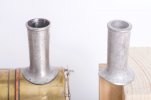
Well, as it happens I had a choice of two chimney castings. This was because the manufacturer of the kit had sent me an extra one for an earlier project, free of charge, and I found it a little too large for the model.
DSC_2408.jpg
I do try to use the right words and to keep my posts brief (honest!) but my "fettling" means boring out the casting to make the chimney look hollow all the way down, tapering the top to make it look like it was made from a thinner material, working the skirt to get the best fit I can manage onto the smokebox, and inserting a peg to let me fix it to the loco. I did put a lot of care into this casting, but my two hours this time might be one hour next time; the boring was especially slow because I was half expecting the casting to tear itself apart.

My own purpose here (as in fitness for) is to be happy. This is a somewhat fluffy and undefined sort of a thing, it's not to do with a shed layout or a garden railway or even my own 7 mm home layout when I decide to start building it, but it does include metalwork, model trains, learning new skills, taking a photograph to send to distant friends, running on a club layout, hauling a train, and being able to tell myself I have made the most of the kit I have bought. These purposes are surely very different to those of the professional model maker, but valid all the same.
 

mickoo

Western Thunderer
Well, as it happens I had a choice of two chimney castings. This was because the manufacturer of the kit had sent me an extra one for an earlier project, free of charge, and I found it a little too large for the model.

View attachment 182952
I do try to use the right words and to keep my posts brief (honest!) but my "fettling" means boring out the casting to make the chimney look hollow all the way down, tapering the top to make it look like it was made from a thinner material, working the skirt to get the best fit I can manage onto the smokebox, and inserting a peg to let me fix it to the loco. I did put a lot of care into this casting, but my two hours this time might be one hour next time; the boring was especially slow because I was half expecting the casting to tear itself apart.

My own purpose here (as in fitness for) is to be happy. This is a somewhat fluffy and undefined sort of a thing, it's not to do with a shed layout or a garden railway or even my own 7 mm home layout when I decide to start building it, but it does include metalwork, model trains, learning new skills, taking a photograph to send to distant friends, running on a club layout, hauling a train, and being able to tell myself I have made the most of the kit I have bought. These purposes are surely very different to those of the professional model maker, but valid all the same.
Absolutely, it's all about being happy and yes, if the original is on the right, then working it to make the one on the left is time well spent and I would probably have done the same; for a commercial model I would more than likely take the cast bolt heads off and fit turned ones.

The important aspect here is what you started with, that is a casting fit for purpose, with some effort...and that amount of effort is more likely defined by skill base....it can be made into something that will look good on the model.

If you were to do another, then your 'effort' would be reduced as you've now acquired the relevant skill sets, allowing you to work with more confidence.
 

mickoo

Western Thunderer
Whilst I wholeheartedly agree, were it not for the recent & growing availability of 3DP, a refusal of the market to accept the less-good castings you showed would lead to a dearth of kits, and fairly rapidly thereafter to no kit makers.

and as we have previously discussed, 3DP is not a panacea. Some things need to be metal for appearance, strength or stiffness.

I fear the dodgy castings issue will be around for a while yet.
Well from my view point (which is like no other...trust me :)) ) if kit makers do not sort this out the people will probably still leave anyway. RTR is showing the way to more detailed models, the internet is awash with more fidelity and detailed models, this is now what people want and the kit market offers subjects that will probably never be made in RTR. That means some tough choices for people and given the rise in demand for fidelity and detail then their footsteps may well reshape the market.
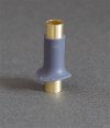
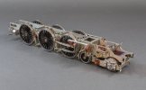
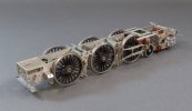
I agree with 3D, it's not the golden goose egg, but in the right application it's a game changer and gives fidelity at a cost clients can stomach. The valve chest covers will be 3D on the King, the bogie spring cups will be turned brass or brass tube sections of the appropriate diameter capped and trimmed off.

I've often used 3D for chimneys, they look good but the taller thinner ones run the risk being damaged over easily, short fat squat ones are not a problem. To that end I've been experimenting with sleeving them with thin wall brass tube. You get the detail and shape accuracy of 3D and a lot of the strength of metal but it has two down sides, the bore isn't tapered and it's slightly under sized.

In this case the requirement was for a brass capped chimney (turned) and 3D base with bolt heads, for reference the brass tube is 6.0 mm OD.

Image1.jpg

The brass tube extends below the base and allows soldering to the metal smokebox wrapper from the inside, the turned cap will then fit over the top and the rim trimmed all flush.

The hardest part was actually printing the chimney wall thin enough to support it's self and remain circular during clean up and post curing, but with a wall thickness of 0.5 it actually just worked as did the thin flange around the base.

It has merit for further testing and I think I might be able to get even thinner wall metal tubing, whether you can get it in the right size is another matter mind.
 

mickoo

Western Thunderer
More JLTRT King, now we're getting to the exciting parts, pimping I believe yoofs call it

Rather a lot going on so I'll try and keep it short, new forward sand boxes, the kit ones are what I think is an older style and compare well with the GA but I opted for the bigger units fitted in later days to some (all?) engines, certainly to the one being modeled.

Next are some internal upper slide bar brackets, they form no load bearing and are just eye candy to bulk out that big space. There's two types in there, the ones with the nuts over the bars are wrong and will be replaced with the other type once the printer has finished. Down below I added a brass dropped section stay for the bogie pivot.

My pivot is set rearward a fraction from dead centre as I wanted less swing at the rear, that way I didn't have to trim the rear axle springs to clear the frames and other metal work. It does mean that there is a little more swing at the front, but then I have more room to play with out there than I do back in under the rear axle.

Finally an inside cylinder block, quite a tricky little beast to get to fit in with the rest of the metal work but it does go in, it's not fixed yet as I still need access to the rear sheet to secure the slide bars and other works forth coming.

Try as I might I cannot find a good low down picture of the cylinder block front, I've added holes for the pressure relief valves to mimic the front end of the outside cylinders, aka, valves below the cover fixing stud but my gut feeling from looking at the GA is that they're higher up and in the middle near the valve covers. I have a reserve print with holes up there just in case.

I've not added the holes for the drain cocks as I think clearance will be too tight to model them, besides there isn't six spare cocks in the kit so I'd need to source some from somewhere, it'd be a nice feature to add with the six pipes just poking out under the buffer beam, the jury is still out on whether they (and associated linkages) get fitted or not.

The cylinder block flared arches protrude a fraction at the moment and the small gap will be filled and then the edge blended in and rounded off.

Bogie mechanical side control is a simple U of sprung steel wire held in place with two small bore brass tubes, it's simple, works well and controls the front end to allow the engine to roll through Peco switches and negotiate 6' curves with no shorts or snags. Vertical springing is on the pivot and a thrust plate/washer on the lower plate of the bogie stay, all held in place with a nut from below.

Finally new 3D bogie side control assemblies, due to my narrowing the rear of the front section (to match the rear section width and not leave a step) the angles of the side plates changed, thus the etch plate no longer presented the right attitude. It seemed an ideal item to print and just for giggles I added the castellated nut and yes it did print, but I did draw the line at adding the split pin.

IMG_12298.jpg

IMG_12299.jpg

IMG_12301.jpg

IMG_12302.jpg

IMG_12304.jpg

IMG_12305.jpg
 
Last edited:

mickoo

Western Thunderer
Hello Mick, here is may take on the King the cylinder vale gear on mine it can be removed through the front. It can be fitted with a pin once painted. You are more than welcome to use the jig I made to fit the ring on the inside, if you choose to use this method.
The bogie swing needed to have a notch in the frame to allow enough float.
Another fine build by you I must say, can’t wait to see the result.
RogerView attachment 182928
View attachment 182927View attachment 182926View attachment 182925View attachment 182924View attachment 182929View attachment 182930View attachment 182931View attachment 182932
Roger, very nice machinist approach, I'm thinking of something similar but my main concern is getting the crossheads out to aid the painter, probably not even possible on the inside set to my mind at the moment. A lot of your castings are much better than the ones I have here and the big olde inside motion bracket looks good in brass, this kit has white metal ones, two actually, both as bad as each other so if it gets added then it'll be another 3D print.

My only hesitation to adding it is that you have to hack all that plate work off the top of the frames, basically the area where the two section are bolted together. I've already opted to not use the bolts and soldered it all solid, but if I take that plate work I'm going to have to add some extra straps on the sides to get some of that strength back, the jury is still out on that.

Your brass expansion link castings look neat, nothing in this box for them, again something I'd have to try and source as 3D is not appropriate for those parts.

Thanks for the photos, nice and clear, they confirm some of the issue I've been having, solves some I've done in a different way and lays some light on future problems and possible solutions.
 

Genghis

Western Thunderer
Quality control is a real issue for kit producers. We inherited about 200 moulds for casting whitemetal when we bought Gladiator. Since then these have been supplemented by about an additional 30 that were produced to improve the quality of castings. We used to get these produced by Graham at NMRS and then by Dave at JPL now both no longer with us. Fortunately we now have another source but otherwise an investment in a vulcanising machine would be required and can we really afford it? We use 4 different casters for lost wax brass, one of whom I now know that I need to check each sprue individually before picking for packing. The others get a passing glance because experience tells me that they are usually fine. We are in the process of migrating our lost wax nickel silver castings as we were paying for a lot of scrap from the original supplier who had the advantage of being cheap but variable in output. But this takes time and investment in new moulds. Since the demised of Photoetch the cost of etches has rocketed and the quality of the alternates we have is not as consistent. It all takes time to check.

We have been migrating castings from whitemetal to lost wax or resin as appropriate but there is a real cost to this. Whitemetal is cheap and relatively easy to work. If the moulds are not too old the quality is OK. Our LNER O4 kit is supplied with three chimneys, two domes, two smokebox doors and a variety of safety valves and washout plugs. If we supplied all of these in brass it would add at least £50 to the price of the kit for contents which will not all be used. So for now we pack the whitemetal and will supply FOC the appropriate brass chimney and dome if we have them. The alternative is either to stock many variations of the same kit or only pack the kit when ordered. But we usually pack 2 or 3 of the same kit at the same time. I pick the parts and Trisha checks that they look OK and that each kit has the same contents. This gives an additional QC check that would be missing otherwise.

But I completely agree that all kit manufacturers, including us, need to up our game.

Dave
 

mickoo

Western Thunderer
Interesting/informative perspective David, one which I'm also marginally involved with in Finney7, though more at the initial design stage than production and packing it has to be said.

Much as I dislike white metal as a medium, I have to openly concede that when cast from fresh moulds it can be exceptionally good and impressive. So, is it worth while exploring new white metal moulds as opposed to migrating to brass, I suspect there will be a cost calculation to consider and future durability/quality.

Kit variations within a kit are a nightmare, in this day of rising costs I doubt new kits will see the same proliferation of bin fodder packed in them. Mind I'm not sure I can see a workaround if people do want variations; you probably need to cast them anyway in case they do, and having done that you may as well pack them!

I note also the use of resin, I think that in certain places it is a good choice, I believe it has less shrinkage than metals, generally cheaper to produce though not sure of mould life. Things like domes, sand boxes, tool boxes are ideal for resin, especially the traditional type which has a longer track record for stability, aka Finney7 A4 and BLP casings etc, or AFV/aircraft/ship modelling.

The only part I changed on the 2P were the rear sand boxes to bring the lids out closer to the valance, a by product of using narrower frames for O fine. I recall the originals were acceptable but failed to compensate for the narrower frames, which with three (I think) sets of spacers in there is always going to be hard to accommodate.

Other than that, everything (castings) else was fine, so you're doing something right :thumbs:
 
Last edited:

mickoo

Western Thunderer
Hello Mick,

some nice work going on. But the parts that you say are the bearing cups for the bogie are for the steam pipes. The bearing pads for the bogie are etches IIRC. The ones for the frames are castings.
View attachment 182970

I do hope that you have the new back head casting.
View attachment 182971
View attachment 182972

ATB

OzzyO.
Ozzy, cheers, that's what those cups are for :)) I was in all honesty guessing, because the instructions do not mark or note any part numbers for the castings, you have a very low contrast photocopied sheet of all the sprues but not a single number or reference, basically it's guess the shape and hope it's the right piece. By good fortune there appears to be some original Malcolm Mitchell sheets in the box, without those you'd be stuffed, even then, some of those are copies of copies and very faint.

I do indeed appear to have the new white metal back heads :thumbs:
 

mickoo

Western Thunderer
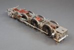
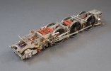
End of another week on the JLTRT King, the chassis is getting there but still quite some way to go, I had hoped to wrap it up by end of play today but it wasn't to be.

The over etching still continues to thwart steady progress, much hacking, adding bits or simply making new is the order of the day, having said that, there's only four more levers to sort and all the NS is done with, the rest will all be scratch built extras.

The ash pan will be the last big 3D part but that won't be added until the motor orientation is resolved, and that won't happen until at least the footplate is on and I've a better idea of the cavity inside the firebox.

IMG_12325.jpg

IMG_12327.jpg

IMG_12328.jpg

IMG_12324.jpg

IMG_12323.jpg
 

mickoo

Western Thunderer
Some assembly may be required.

Collected from that lovely Mr Crayons Heywood today, just have to find the tubs with all the remaining bits and put them all back together in the right order :eek:

And yes, the Garratt Jekyll and Hyde disorder has been spotted and will be corrected before weathering :cool:

IMG_12345.jpg

IMG_12349.jpg
 
Last edited:

mickoo

Western Thunderer
JLTRT King Chassis all complete. I'll add the sand pipes after paint and I need to source some oil pots for the piston glands and add the associated pipework. It looks like the gearbox will not foul the base of the ash pan, but to be sure I'm going to wait until I know exactly where the unit is going to sit before drawing it up in 3D.

Other than the inside crossheads all the remaining motion can be removed to aid painting and the whole lot has been run in for several hours already, it'll get many more later on before delivery.
IMG_12354.jpg

IMG_12357.jpg

IMG_12358.jpg

IMG_12360.jpg
 

Compton castle

Western Thunderer
It’s a pleasure to see this one come together as this loco is for a good mate of mine so I’ll get to see it a lot and it’ll no doubt feature on a few of my layout builds.
I can see this one along with another king on train 131 the relief to the Cornish Riviera, the only scheduled train to regularly feature double headed kings over the south Devon banks!
Magic
 

mickoo

Western Thunderer
It’s a pleasure to see this one come together as this loco is for a good mate of mine so I’ll get to see it a lot and it’ll no doubt feature on a few of my layout builds.
I can see this one along with another king on train 131 the relief to the Cornish Riviera, the only scheduled train to regularly feature double headed kings over the south Devon banks!
Magic
Other than the over etched nickel silver and quite a few brass castings not up to scratch it's actually been pretty good.

I may turn some more bogie bearing cups that are a little deeper and close that gap up a little more, I did toy with making sprung ones and it's not technically difficult to do.
 

mickoo

Western Thunderer
Small update on the JLTRT King, happily the brass upper work etches are just fine and everything's fits lovely.

The bulk of the footplate and cab structure is done, enough to check squareness, alignment and fit onto the chassis and check it all levels up with the tender etc.

It's now just a case of joining all the dots up with the remaining bits and details before moving onto the hot wet bit.

IMG_2381.jpg

IMG_2382.jpg

IMG_2379.jpg
 

mickoo

Western Thunderer
Finally getting some real progress done, there's always a bit of trepidation when mating the boiler with the footplate, little niggle here, little niggle there, usually the smoke box saddle has the wrong radius or the splasher cut outs in the firebox side are a smidge out, not so in this case, all the bits formed perfectly and all slot together just beautifully.

On the whole, the brass etches are really good to work with and soaking a lot of the previous nickel silver pain away.

The only change I've made is to blank in the top of the fire iron tunnel as that appears to be the norm in later BR days, much like modified Halls. In reality the top plate should be perfectly flat with the splasher tops but that would have meant a lot of hacking and potentially leaving the door open to Captain cock up and his crew. The middle splasher joint will be hidden by the name plate and top feed pipe, the rear one by the top feed pipe so little need to get excited and create work for little gain.

The whole boiler assembly is not yet fully fitted as I need to get the sanding rods and reversing reach rod all in place first, that means there are a few gaps twixt firebox sides and splashers/footplate to fill and clean up.

I wasn't sure if the 3D reservoirs over the intermediate driver would be seen once everything is in place, they are and form a nice little light blocking filler and add a bit of mass down there.

Now that the boiler is all in place I can set the motor angle/location and then work around it with the 3D ashpan and get that done to finish off the chassis.

IMG_12389.jpg

IMG_12390.jpg

IMG_12392.jpg
 
Last edited:
Top