Michael's tool bench and other model stuff

michael mott

Western Thunderer
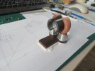
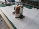
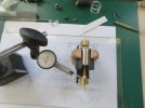
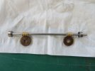
Here are a few pictures of the articulated sanding tool I mentioned on Heather's thread

I made this little sander to sand the 75 year old painted surface of a damaged Basset Lowke steamship model.

The foundation of the pad was the clevis or control rod ends for radio control model aircraft.
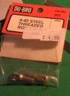
Capture control ends.JPG

This was attached to the end of some 3/16 hex steel stock.
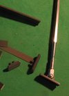
Capture8464.JPG

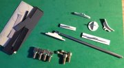
The pads can be made from a number of different plastic sections either commercial such as Plastruct or Evergreen sections
or simply fabricated to suit
Capture2080.JPG

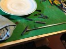
The key is to make them able to snap on and off for ease of switching forms or sizes.
IMG_1463x1024.jpg

I primarily used wet and dry and simple kept it clean by dipping the pads in a saucer of clean water.

I hope this is helpful

Michael
 
Last edited:

michael mott

Western Thunderer
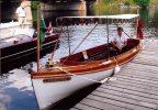
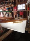
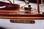
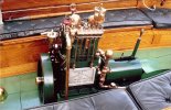
So I have another thread in my genetic model make up, and it is model boats. I have been working on this model for some time I started with the Buffalo 2 hp engine in 1/8th scale it is for a 1909 open launch that was one of a pair built for Andrew Mellon. It has changed hands a few times and has been completely restored by a chap in Ontario. First some pictures of the full size boat, it is 19 feet long with a beam of 4 foot seven inches.
scan0004x1024.jpg

Bow three quarter.JPG

Name board.jpg


scan0006.jpg

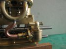
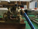
And the model engine.

IMG_5430x1024.jpg

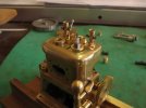
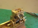
There is a planetary gear set inside the drum that reverses the propeller when it is clamped.

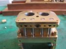
The spark plugs do work and the cylinders have a water jacket.

IMG_5672x800.jpg

The cam and valves
IMG_5802x800.jpg

The manifold was a bit tricky to bend, I used a styrene rod inside then burned it out after bending. the carb is one that will use vapor from the gas tank.
IMG_5941x800.jpg

IMG_5944x1024.jpg

IMG_5952x1024.jpg

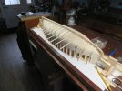
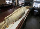
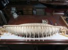
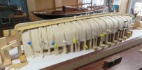
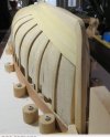
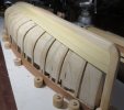
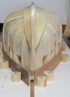
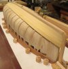
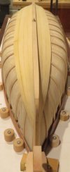
And the hull at the moment.

IMG_4127x1024.jpg

IMG_4128x1024.jpg

IMG_4129x1024.jpg

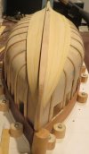
The hull was planked in yellow cedar, and my model will be as well.
It occurred to me that I could put the model on a flat wagon that was shipping the boat by rail across country..

Michael
 

michael mott

Western Thunderer
Michael, Phil, Mark, and Chas, thank you for your kind remarks. and for everyone who added the likes.
I fell off my chair when I scrolled down to the picture with the pencil.
Ah yes the giant pencil does it every time :)

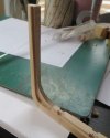
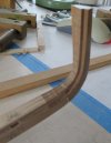
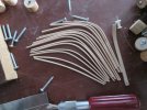
A bit of work on bending the frames and shaping the stem and stern.
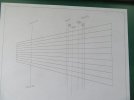
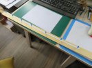
I used a chart to help lay out the positions of the ten planks using strips of paper.
IMG_4151x1024.jpg
This was used to find the width of the garboard plank or strake.

IMG_4150x1024.jpg
The planking is of yellow cedar a scale 3/4" thick with is 3/32" in real money (imperial)
These planks were formed using a hot air gun and a lot of trial and error fitting and bending.

Capture4157.JPG
Capture4159.JPG
The planks are just resting there the pins just stopping them from sliding off.
the stem and stern posts fully shaped .
Capture4162.JPG

Capture4161.JPG

The ribs are scale 1/2 " x 1 1/2"

IMG_4167x1024.jpg
Top

It is nice to have a change of pace from brass work and lathe work.

Michael
 

michael mott

Western Thunderer
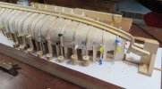
The laying of the planks is a challenge here the first three on the port side and two on the starboard side I am using a hot air soldering gun to shape the planks before gluing.
Capture4196.JPG

Capture4197.JPG

Capture4203.JPG

There are ten planks and the shape of each will begin to change dramatically as I come closer to the turn or thr bilge at midships.
the planks are a scale 3/4 in which is 3/32 actual.

Michael
 

paulc

Western Thunderer
I have lost count of how many times i scrolled up and down through all the pictures . This is modelling on a totally different level .
Fantastic work Michael .
PS I'm a sucker for the style of boat next to the one you're modelling in the first photo .
 

michael mott

Western Thunderer
Another small update in between working on a small photo layout of the entrance to a slate mine with a stub point and a large rock face in order to be able to photograph my No 5 Penrhyn loco.
the planking is a little stressful because I am trying to follow the real boats 10 planks.

Capture4208.JPGCapture4210.JPGCapture4211.JPG

michael
 

michael mott

Western Thunderer
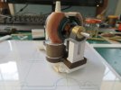
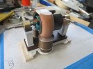
Not being one of those people who can work on only one project at a time, and having an affection for the early victorian experimental electric motors, I came across another one that was begging to be modelled, and having another old battery drill motor that are easy to rework into some fantasy loco. I have begun another to add to the collection. These are fun to do because they are not nearly as stressfulas working on accurate representations of real boats and locos.

IMG_4323x1024.jpg

IMG_4322x1024.jpg

I glued the ceramic magnets to the wood supports and to get the correct position for the armature I have placed a round of aluminium between them that is 40 thou larger in diameter than the actual armature. I will slide a shaft through the middle of the aluminium in order to set the supports up accurately. The aluminium bobbins will get some braided wire wrapped around them and the terminals will attach to a plate above the support "Irons" The brushes will be able to rotate to obtain the optimal position for the motor in the same way at the real one.

Michael


o
 
Last edited:
michael mott

Western Thunderer
A lot of fiddling around and I think I will have a workable set up soon.
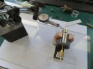
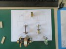
After adding the shaft in the aluminium keeper I worked on the bearing pedestals. and then made the adjustments until I got a 0 reading at each end.
IMG_4327x1024.jpg
IMG_4330x1024.jpg

I discovered that I needed to prevent the magnets from rotating toward each other at the open end (I probably should have seen that coming earlier) so added a styrene plate top and bottom to prevent the rotation. The only other addition so far was to add some length to the output end of the rotor so Bored out a short piece of 3/16 drill rod and loctited it to the the shaft. This will allow me to mount a Servo-link sprocket to drive the wheels.

IMG_4336x1024.jpg

IMG_4338x1024.jpg

I did a test with the original set of brushes in the original end cap cut down so that it was easy to rotate and it ran beautifully, So now to design and make a refined looking set of brushes, and the top plate with the terminals. Then it can be painted. The spools are wound with a heavy cotton thread. Guttermann 50 Cne.

Michael
 

michael mott

Western Thunderer
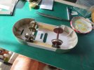
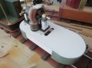
Started roughing up the loco frame today
IMG_4351x1024.jpg

The wheel bearings are some rigid PVC profile I made some years ago, I sliced off 4 bits a 1/4 inch wide.

IMG_4356x1024.jpg

A mix of cards and some 1/2 inch square yellow cedar. The ends are a laminate of shreddies cereal box and some old green file dividers the white is some Archival Matt Board.

Michael
 

michael mott

Western Thunderer
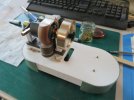
Did a test run today
I did the run without the flywheel
IMG_4365x1024.jpg

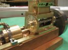
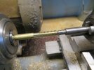
I had a couple of worm gears that are 16 teeth to the inch so set up the Myford to make the worms, It is a chore resetting the change wheels, Oh for a Myford quick change Gearbox.

IMG_4360x1024.jpg

IMG_4361x1024.jpg

IMG_4360x1024.jpg

And set up between wood pillow blocks with salvaged 3/8 x 1/8th ball races that a friend who was a helicopter maintenance man gave me years ago, apparently they replace these bearings after 100 hours, They are good enough for my needs. I have enough to last several lifetimes.

IMG_4364x1024.jpg
A bit eccentric to be mounting ball races in wood pillow blocks, but given that the frame is card why not.

Michael
 
Top