NickB
Western Thunderer
Now, where were we? Oh yes, tyres. Warning: this post is about turning tyres, so if you have no interest at all in lathe work, you may decide it is not for you. Feel free to move on.
And if you're one of those annoying people with a toolroom quality lathe and a zillion years' experience, this post certainly isn't for you. I'm not in your league. I'm one of those people who thought it would be fun to have a lathe and went on from there.
The first task is to reduce the blank to thickness and bore out the ID to the correct size. My chuck was only just big enough, but it did hold them securely. I used a headstock backstop so that each blank goes in the same position, and a carriage stop to avoid running into it with the boring bar. All the tyres were done using this setup before moving on.
The lesson here was the layer of hardened material that is formed by the heat of the laser at the cut edges. Reminiscent of the skin on the sand casting beloved by model engineers of a certain generation. Not tool steel hard, it does cut, but takes it out on the tool.
I was expecting that, but I was surprised how deep it was - up to 0.8mm in my case. It dulled the edge of an HSS tool very quickly. Yes, I'm still in the 20th century for lathe tools but I mostly use HSS tools because so much of the turning that I do requires a special tool form to be ground and it's a lot easier in HSS.
That was certainly true until I discovered that the awkward bits could be 3D printed.
Anyway, I switched to a carbide insert boring bar which did a much better job of cutting. The only tool I had available is much longer than I needed so it vibrates a bit and the quality of the finish is not great. But I will be gluing the centre in place, and a slightly rough finish (this isn't an argument for a ploughed field finish) means a greater surface area in contact with the glue which is all to the good.

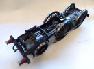
Once the ID is correct the tyres go on this fixture. Where the tyre is mounted it is turned in situ to a good running fit on the tyre ID. Then it never leaves the chuck until the whole batch is done to ensure that the tyres are concentric.

Each tyre is clamped in position, and the first task is to reduce the OD to the diameter over the flange. Again there is a layer of hardened material to get rid of and I used a carbide insert tool for this. Incidentally, when I ordered the tyre blanks from the cutting firm, I did add enough margin on both ID and OD - just. Phew.

Now to form the profile. Lock the saddle and set the top slide over at 3 deg to give the correct taper on the tyre. The tool is moved exclusively by the top and cross slides in this operation. The leading edge of the tool is set at the correct angle for the flange. Then cut to final diameter plus a very small margin (say, 0.05 mm or a couple of thou in old money).

Now for the controversial bit! I get the final shape using a form tool (from Mark Wood). I like it because the final profile is entirely consistent. Lock everything that can be locked on the lathe, use a very slow speed and feed the tool in slowly. If you do it right and keep the final cut very fine, it doesn't chatter.
People have told me they can get just as good a finish with conventional tooling and the form tool isn't worth the cost. I just checked and I see that the cost is almost double what I paid about eight years ago, so you might think twice about it. Anyway, I've done about 40 tyres in G3 so far so it's beginning to pay for itself.

We're still not quite finished. The surface needs some attention with a fine file (I know, sacrilege) and wet-and-dry paper. Then it is finally done.

Rinse and repeat twenty times. A pile of finished tyres is gradually building.

That's it. There are lots of instructions on the web about how to turn wheels from castings, but I decided to set out how I did it from laser cut blanks, which isn't quite the same. If you stayed the course, thanks for your company.
Nick
And if you're one of those annoying people with a toolroom quality lathe and a zillion years' experience, this post certainly isn't for you. I'm not in your league. I'm one of those people who thought it would be fun to have a lathe and went on from there.
The first task is to reduce the blank to thickness and bore out the ID to the correct size. My chuck was only just big enough, but it did hold them securely. I used a headstock backstop so that each blank goes in the same position, and a carriage stop to avoid running into it with the boring bar. All the tyres were done using this setup before moving on.
The lesson here was the layer of hardened material that is formed by the heat of the laser at the cut edges. Reminiscent of the skin on the sand casting beloved by model engineers of a certain generation. Not tool steel hard, it does cut, but takes it out on the tool.
I was expecting that, but I was surprised how deep it was - up to 0.8mm in my case. It dulled the edge of an HSS tool very quickly. Yes, I'm still in the 20th century for lathe tools but I mostly use HSS tools because so much of the turning that I do requires a special tool form to be ground and it's a lot easier in HSS.
That was certainly true until I discovered that the awkward bits could be 3D printed.
Anyway, I switched to a carbide insert boring bar which did a much better job of cutting. The only tool I had available is much longer than I needed so it vibrates a bit and the quality of the finish is not great. But I will be gluing the centre in place, and a slightly rough finish (this isn't an argument for a ploughed field finish) means a greater surface area in contact with the glue which is all to the good.
Once the ID is correct the tyres go on this fixture. Where the tyre is mounted it is turned in situ to a good running fit on the tyre ID. Then it never leaves the chuck until the whole batch is done to ensure that the tyres are concentric.
Each tyre is clamped in position, and the first task is to reduce the OD to the diameter over the flange. Again there is a layer of hardened material to get rid of and I used a carbide insert tool for this. Incidentally, when I ordered the tyre blanks from the cutting firm, I did add enough margin on both ID and OD - just. Phew.
Now to form the profile. Lock the saddle and set the top slide over at 3 deg to give the correct taper on the tyre. The tool is moved exclusively by the top and cross slides in this operation. The leading edge of the tool is set at the correct angle for the flange. Then cut to final diameter plus a very small margin (say, 0.05 mm or a couple of thou in old money).
Now for the controversial bit! I get the final shape using a form tool (from Mark Wood). I like it because the final profile is entirely consistent. Lock everything that can be locked on the lathe, use a very slow speed and feed the tool in slowly. If you do it right and keep the final cut very fine, it doesn't chatter.
People have told me they can get just as good a finish with conventional tooling and the form tool isn't worth the cost. I just checked and I see that the cost is almost double what I paid about eight years ago, so you might think twice about it. Anyway, I've done about 40 tyres in G3 so far so it's beginning to pay for itself.
We're still not quite finished. The surface needs some attention with a fine file (I know, sacrilege) and wet-and-dry paper. Then it is finally done.
Rinse and repeat twenty times. A pile of finished tyres is gradually building.
That's it. There are lots of instructions on the web about how to turn wheels from castings, but I decided to set out how I did it from laser cut blanks, which isn't quite the same. If you stayed the course, thanks for your company.
Nick
")


")