1/32 LMS 4-4-0 class 2P

michael mott

Western Thunderer
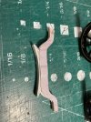
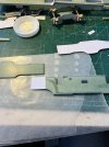
After doing a test assembly of equalization beam with the spring, it’s apparent that the way I have interpreted the beam will not work. IMG_1298.jpeg
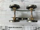
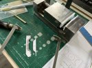
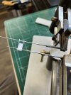
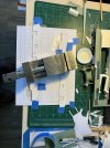
This caused a bit of a rethink as how to make the beams stepped. The beams are 1” thick and the printable card stock is.008” thick so 4 laminations =.032 basically 1 “. I decided to try to form the shape by making a small press using layers of styrene and then using a diluted carpenters glue 50/50 with water. I coated the two inner layers both sides with the glue and the outer layers only on the insides quickly sandwiched the stack between the forms.
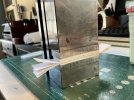
IMG_1299.jpeg
Let it set up for another 15 minutes before removing it from the press (vice)
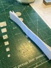
IMG_1302.jpeg
First test confirmed the principle. Next to use a print of the beam registered so that it will facilitate cutting it out once the glue has fully dried.
Michael
 

michael mott

Western Thunderer
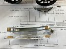
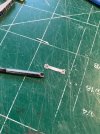
The new method is working well after laminating the 4 pieces and leaving them to harden up I was able to use the jewelers saw to cut the first two out
IMG_1303x1024.jpg
and glue them together with the proper 3" spacer at the ends the centre section is 6 inches as per the drawings.

IMG_1307x1024.jpg

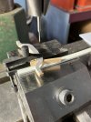
After using some spacers the holes for the sping hangers were able to be drilled easily

IMG_1304x1024.jpg

Now to follow up with the next set and drill the holes for the pins to rest on top of the Axleboxes and make new springs.

Michael
 

David Waite

Western Thunderer
Hi Michael
I am enjoying your build immensely, I have just been looking back at your plans you are working from and on 17 April you mentioned you have drawn your own I don’t know how I missed that, how did you do such perfect colourful plans they are amazing.
David.
 

michael mott

Western Thunderer
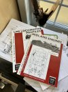
Hi David I purchased the the profile books from wild swan publications and have been studying the drawings in them and building a set for myself that I can use to isolate and print parts. I am using an old version of autocad it is autocad lt 2000 and is all I need for 2D drawing. I do have to keep a computer with Windows XP in order to use it I know that I can run it in a shell inside windows 7 but that is a pain. What I have is working so I will continue to use it.IMG_1310.jpeg
Here is the beam with the spring slipped in between waiting for the hangers IMG_1308.jpeg
Michael
 

Roger Pound

Western Thunderer
I am using an old version of autocad it is autocad lt 2000 and is all I need for 2D drawing. I do have to keep a computer with Windows XP in order to use it I know that I can run it in a shell inside windows 7 but that is a pain. What I have is working so I will continue to use it.

Michael
Proving the old adage, Michael - "If it ain't broke......." :)

I continue to be fascinated by your work and patience and look forward to seeing the 2P on the road in due course. :thumbs:

Roger.
 

michael mott

Western Thunderer
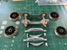
Almost ready to assemble the bogie parts. Slow going, but that is how it is these days.
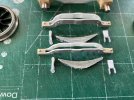
Gluing up the spring hangers the tapered broaches are great for holding small delicate parts. .008" card stock in assorted laminations for the hangers, plasticized with CA glue.
IMG_1311x1024.jpg

In order to round the ends of the hangers I made a small punch like cutter out of some 1/8th silver steel
IMG_1315x1024.jpg

Mostly card and wood, the pins are brass.

IMG_1319x1024.jpg

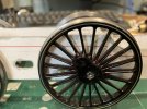
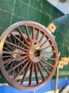
I need to repaint the wheels as the black layer obviously did not adhere to the crimson underneath , so a soak in some lacquer thinner will be in order before repainting.
IMG_1318x1024.jpg
I will use the airbrush next time as well.

Michael
 

michael mott

Western Thunderer
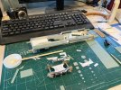
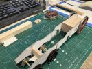
Today I opened up the drawer with the P2 loco and it took me about an hour to get my head around what was what. Started working on the final push to get the front bogie finished.
IMG_1888.jpeg
IMG_1887.jpeg

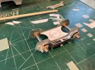
The basic shape of the complex casting has been glued between the frames. I am going to have to do some more work to loosen up all the sliding parts they are a bit too tight at the moment. I have been following the thread about the equalizer springing and am wondering about working something like that for the bogie wheels.
It feels good to be working on this loco again.
Michael
 

michael mott

Western Thunderer
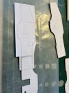
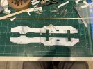
I am also making new frames based on the more detailed information in the LMS profile these new frames are also of the correct thickness. TodayI glued together the front and rear portions of the frames with the 3/16 spacer between them.The first picture shows the rear frame laid over the 3/16 spacer and glued with diluted carpenter glue.IMG_1893.jpeg
This was trimmed afterwards, and now ready to be glued to the front frame
IMG_1894.jpeg
Finally both frames are glued and weighted while they set.
IMG_1895.jpeg
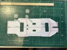
The two parts of the frames were lined up over a print of the full frame.
Michael
 

michael mott

Western Thunderer
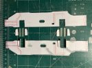
Thinking about the discussion that is about cutting brass sheet and the comments relating to only gluing on one side of a sheet, I realized that I had created just this condition on the new frames. So stepping back I changed tack and decided to laminate a thinner sheet on each side this also gave me the opportunity to print both inside and outside of the frame, the key issue being one of registration. So after a few practice runs with “handing” a folded print was the answer.
After the laminate was set the thickness was.033 inch three quarters of a tho over the scale 1 inch of .03125” I can live with that. (Just kidding) I trimmed the sides.IMG_1898.jpeg

Next was setting up the horn guides a bit of compromise on the shape by using only the shape of the main bearing or the forward set these are built from a couple of different thicknesses of card.
IMG_1900.jpeg
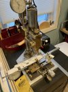
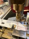
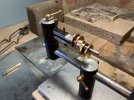
Next I used my homemade drillpress to drill the holes for the retaining bolts. Grant line 2 - 1/2 inch hex bolts for O gauge looked good.
IMG_1901.jpeg
IMG_1903.jpeg
Once the bolts are glued in I will make the bottom block of the castings I will pre drill them before gluing to the rest of the assembly.
Michael
 

King Crab

Western Thunderer
Thinking about the discussion that is about cutting brass sheet and the comments relating to only gluing on one side of a sheet, I realized that I had created just this condition on the new frames. So stepping back I changed tack and decided to laminate a thinner sheet on each side this also gave me the opportunity to print both inside and outside of the frame, the key issue being one of registration. So after a few practice runs with “handing” a folded print was the answer.
After the laminate was set the thickness was.033 inch three quarters of a tho over the scale 1 inch of .03125” I can live with that. (Just kidding) I trimmed the sides.View attachment 198903

Next was setting up the horn guides a bit of compromise on the shape by using only the shape of the main bearing or the forward set these are built from a couple of different thicknesses of card.
View attachment 198904
Next I used my homemade drillpress to drill the holes for the retaining bolts. Grant line 2 - 1/2 inch hex bolts for O gauge looked good.
View attachment 198905
View attachment 198906
Once the bolts are glued in I will make the bottom block of the castings I will pre drill them before gluing to the rest of the assembly.
Michael

That drill press is a masterpiece!
What a beauty.
More details please

Peter
 

michael mott

Western Thunderer
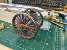
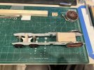
I’m getting a better idea of what I need to do next with the frames. And I have modified the cast iron wheels to make them easier to work with by fitting them with some 1/8 inch square tubes which will also facilitate the quartering, this will also allow for simplified bearing blocks.
IMG_1913.jpeg
Once the tubes are epoxied in place and the 1/4 inch bearing sleeves are soldered onto the 1/8 inch square steel axles I will be able to assemble them with some 2x56 brass pan head screws, which I still have to make.
IMG_1910.jpeg

Time to head in for bed.
Michael
PS
Peter I will address the drillpress tomorrow.
 

Roger Pound

Western Thunderer
Michael,

I have just been catching up on the latest 2P developments. Your pursuit of improvement is to be admired as is your apparent endless supply of patience. The manufacture of the revised frames is fascinating and I look forward to seeing the loco up and running in the fullness of time.
Although the prototype was not the best of internal design, it nevertheless remained the most economical locomotive in terms of running expenses on the LMS books according to comments I have seen elsewhere. I loved them and they took me a few miles in my time as a lad travelling to see relatives .
Keep up with the good work and look after yourself.

Roger :thumbs:
 

michael mott

Western Thunderer
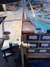
Thank you Roger, even though I have been working to improve the accuracy of the model, by choosing unconventional methods and materials I am finding it challenging to get some aspects as per the full size loco. Because I am using wheels that were originally designed for a different type of loco and 10mm scale, even though they are the correct diameter scale wise the are a little too thick. A scale 6 inches instead of 5. I was able to thin then from their original thickness. By choosing wood for the main wheel bearings there are limits to how thin some sections can be before loosing integrity. I’m using Costello Boxwood which is very dense and stable and by making the wheels fix to the axles in a similar manner as the Slaters wheels I can avoid making split bearings which I have done on a couple of metal models. My plan to make some capture screws like a cheese head screw although worked it did not work well so I changed to a 2x56 flat head cap screw with a counter sunk thick washer, proving to be a better option.
IMG_1917.jpeg
IMG_1918.jpeg

Next to build the main axle so that I can show the inside motion, I sense a challenge coming up.
Michael
 

michael mott

Western Thunderer
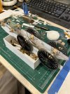
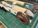
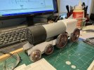
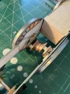
To give the frame some solid rigidity and strength I have glued in the bottom part of the firebox. A bit of cheating because the frames are slightly narrower than the real life frames to accommodate the thicker wheels, I made a 3/4 inch relief where the firebox shows through the frame and added some stays painted it black before gluing it in place. The front frames are 2 inches narrower inside so the spacer is set up as the bearing block for the front bogie. The cylinder form and detail will be added to the front frame spacer once it is made and finished. I n order to minimize stress on the locomotive I have decided to use the tender as the drive unit.
IMG_1926.jpeg
IMG_1927.jpeg

IMG_1925.jpeg

Michael
 

michael mott

Western Thunderer
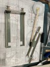
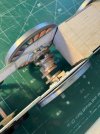
The main axle was a ton of work lots of pauses to make sure things were lined up properly. Used the third hand to solder up the main cranks. I left the 4 central cams loose for the time being, but before placing them between the cranks I put a .025” hole into the narrow side so that they can be pinned later after the link arms are setup.IMG_1929.jpeg
Next I used the jewelers saw and removed the central pivots.
IMG_1933.jpeg

Lots of filing later and the were ready for a final pickle to clean it up.

IMG_1936.jpeg
IMG_1937.jpeg
IMG_1939.jpeg

I’m a happy camper at this point.

Michael
 

michael mott
Western Thunderer
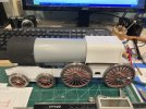
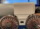
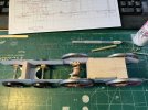
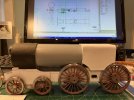
Discovered that the firebox is a little too long from the model drawing that I originally followed which makes the wheel clearance’s wrong as well. The boiler and smokebox are okay IMG_1941.jpeg
IMG_1942.jpeg
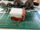
So a new firebox is in order now. However I decided to rework the old one so chopped off the bottom of the sides and shortened it up the appropriate amount.

IMG_1943.jpeg

Then glued it back together.
IMG_1944.jpeg

Then printed up the new configuration and glued the card pattern to the inside of firebox tomorrow morning I can print up a second set and stick them to the same thick card and use the inner sheet as a reference to position the thicker card.
IMG_1946.jpeg
Michael
 
Last edited:
Top