Hornby T9 in EM Gauge

Stevers

Western Thunderer
The T9 had a successful run on South Junction, but given the false flat induced by the drainage slope on the chicken shed floor, only four Kitmasters could be hauled round the Canal End with those Nickel Slither tyres fitted. The pickup PCB will need to be altered as there isn't quite room for the now demountable brakes to be re-fitted. So near and yet so far...

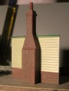
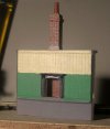
On returning from the chicken shed I bit the bullet and made a start on a 3D model of the LSWR Type 1 signal cabin at Verwood, which has taken most of my free time since then:
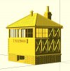
SB Front and Canopy Side.jpg
In the past, an inordinate amount of time has been spent producing drawings for the box to be laser cut and etched in no less than five different materials to still not achieve the effect I wanted after a lot of messing about with glue. Having looked into laser etching further, I now think the process has too many technical limitations, and 3D Printing is the way forward. If anyone wants such a box, or if there's any interest in how I got this far, let me know and I'll start a dedicated thread.
 

Stevers

Western Thunderer
After a hiatus for the signal box and to finish the heavy metal monster (Wills T9), the Hornby T9 is back on the agenda.
P1010302.JPG
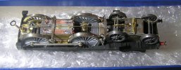
Following the problems with fitting the brake gear, I had tried moving the backscratcher pickups to a more conventional location under the motor. As feared, it was a terribly tight squeeze. The backscratchers had the potential to short onto the live Markit wheels centres if out of adjustment, and in this configuration it never ran successfully with the body on. More troubling was that the chassis was live when it shouldn't be. Anyway, after a happy couple of hours the pickups are now underneath DCC expert style, but in PB wire. I had to thin and fret out the original copperclad fibreglass mount so that it was less visible and cleared the brake gear. The pickups work through the full vertical movement of the wheelsets, and acting where they do, they level the chassis when it runs standalone as a 'power pod'. The motor PCB was found to be a tight fit against the frames, and chamfering the sides eliminated the short to the chassis. All the extra lead filling the many voids between the Perseverance chassis frames is now fitted and on Wednesday I'll take it down to CS2 to see how it runs body on, fully weighted, with all brake gear and linkages in place. There are two lumps of lead underneath the pickup PCB each side of a cross member, a lump of lead ahead of the front driven axles and more lead and a solid brass drag box under the cab.

Next up I need to make some more injectors as per the Wills T9, and I can think about painting the chassis, and changing over to the AGW wheels - it would be nice to think that there really will be room for some paint in there!
 

AdeMoore

Western Thunderer
The T9 had a successful run on South Junction, but given the false flat induced by the drainage slope on the chicken shed floor, only four Kitmasters could be hauled round the Canal End with those Nickel Slither tyres fitted. The pickup PCB will need to be altered as there isn't quite room for the now demountable brakes to be re-fitted. So near and yet so far...

On returning from the chicken shed I bit the bullet and made a start on a 3D model of the LSWR Type 1 signal cabin at Verwood, which has taken most of my free time since then:
View attachment 155928
In the past, an inordinate amount of time has been spent producing drawings for the box to be laser cut and etched in no less than five different materials to still not achieve the effect I wanted after a lot of messing about with glue. Having looked into laser etching further, I now think the process has too many technical limitations, and 3D Printing is the way forward. If anyone wants such a box, or if there's any interest in how I got this far, let me know and I'll start a dedicated thread.
Very interesting , be intererested in that. Tag me in it if you start a new thread.
 

NHY 581

Western Thunderer
On returning from the chicken shed I bit the bullet and made a start on a 3D model of the LSWR Type 1 signal cabin at Verwood, which has taken most of my free time since then:
View attachment 155928
In the past, an inordinate amount of time has been spent producing drawings for the box to be laser cut and etched in no less than five different materials to still not achieve the effect I wanted after a lot of messing about with glue. Having looked into laser etching further, I now think the process has too many technical limitations, and 3D Printing is the way forward. If anyone wants such a box, or if there's any interest in how I got this far, let me know and I'll start a dedicated thread.

Plus one for me. That looks great.

Rob.
 

Stevers

Western Thunderer
Having finally made it down to the clubroom, I am happy to report that the little T9, with all weight fitted, managed seven coaches over the 'hump' on the otherwise now perfectly level South Junction. The green Kitmaster MK1s used for the test have variable running qualities and one of them obviously had the brakes seized on, and that may have been in the consist for the previous test run when only four coaches could be managed. Running qualities were excellent, other than the borrowed wobbly Sharman front bogie wheel, that every few loops would get caught up in the pointwork.

Next job on the T9 will be to paint the chassis and fit a full set of AGW wheels. I also need to think about modding those 'wide cab' cab cutouts - I have a cunning plan and have even cut metal!
P9230347.JPG
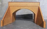
Today's project is to start painting the laser cut over bridge that I have designed for Verwood, but I'll start a separate thread for that.
 
Last edited:
Top