7mm David Andrews Princess - 6206 Princess Marie Louise

OzzyO

Western Thunderer
Hello Rob,

the real things did not just pivot out and back . But to get them to move you had to lift the bottom edge by about 1/2" and then put them into position, you could not lift them to high so there was no possibility of losing one of them on the road, the closed position was normally used for cleaning the front face of the guards, so you did not have to reach too far outside of the loco. The bracket also locked them in place out (open) folded back (closed I suppose).

Now lets see you do that.

And the door was shut, I did not have time to get my hat and coat and it's raining cats and dogs.

ATB

OzzyO.

PS, let me know and I'll do you a quick sketch
 

Rob Pulham

Western Thunderer
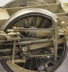
The last week or so has been spent on lots of little jobs that don't seem to change much visibly on the model. The visible bits are the trimming of the cylinder drain pipes and having to rethink how I planned to mount and retain the motor from moving.

I also milled a hex on the ends of the front crank pins to replicate the fitting on the prototype.

53656683902_bc2fb2d5d1_b.jpg

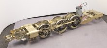
I had initially envisaged that the mtor would sit flat and I did add a nut on to a frame spacer to retain it via a strap around the motor but it wouldn't fit through the hole in the firebox with it in this position. My final solution was to replace the rear frame spacer with one that is removable. This was needed because the large final drive gear on the ABC gearbox wouldn't pass between the gap under the existing frame spacer and the top of the rear frame section. A different motor gearbox combination might not have needed this solution.

Now that it's removable, the motor/gearbox can be lifted out for maintenance etc. and the position of the spacer once fitted, also acts as a stay preventing the gearbox from rotating about the axle. Win, win.

53656684387_fc4ebb6672_b.jpg
 

40057

Western Thunderer
The last week or so has been spent on lots of little jobs that don't seem to change much visibly on the model. The visible bits are the trimming of the cylinder drain pipes and having to rethink how I planned to mount and retain the motor from moving.

I also milled a hex on the ends of the front crank pins to replicate the fitting on the prototype.

View attachment 213728

I had initially envisaged that the mtor would sit flat and I did add a nut on to a frame spacer to retain it via a strap around the motor but it wouldn't fit through the hole in the firebox with it in this position. My final solution was to replace the rear frame spacer with one that is removable. This was needed because the large final drive gear on the ABC gearbox wouldn't pass between the gap under the existing frame spacer and the top of the rear frame section. A different motor gearbox combination might not have needed this solution.

Now that it's removable, the motor/gearbox can be lifted out for maintenance etc. and the position of the spacer once fitted, also acts as a stay preventing the gearbox from rotating about the axle. Win, win.

View attachment 213729

That’s a really nice looking model.

As someone who is used to vintage models, the thing that leaps out at me is what a tiny motor is such a large locomotive. Astonishing that it can power something that size.
 

Rob Pulham

Western Thunderer
One of the things that I have never been entirely happy with on previous locos is the fitting of additional lead weight to the boiler. Tank engines are a bit simpler because the lead sheet can be fixed in the tanks and enclosed. It's not so much the fitting of the lead, so much as how to retain it and stop it from shifting over time.

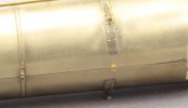
Previously where needed I have used epoxy or 100 degree solder to fix it in place (I have built a number of DJH kits and on those the weight of the cast boiler was more than enough without adding additional weight). This time I thought I would try a different method first I rolled up some sheet lead and then some adjustment to make it fit. I used a hollow punch to cut out a section to fit around the base of the top feed which helped to hold the lump of lead in place next I drilled the bottom of the boiler being careful to site the hole behind the middle splasher so it wouldn't be seen from the side. Then I tapped the hole as deep as I could 10ba and then screwed in a 1 inch 10 ba screw being soft lead once the screw got beyond the tapped section it continued to cut it's own thread and now the ballast is held firmly in place.

53668508201_9639e6f446_b.jpg

53668720308_91067de6c9_b.jpg

53668720258_d66e11aa75_b.jpg

I would be interested in the methods used by other builders to retain lead ballast in boilers.
 

daifly

Western Thunderer
Rob

I was concerned at first that the boiler wasn't resting with its bottom at the lowest point. On looking again at the first photo, I was relieved to see that the presence of a delicate cleat would have been more than enough to offset the lie of the boiler!

That looks as if the wheels should be firmly pressed into the railheads!

Dave
 

spikey faz

Western Thunderer
Rob

Apart from adding some lead to the front of my Southern crane loco (to help balance the rear overhang) I don't think I've added any lead weight to any of my loco builds. I've never really felt the need to do so as they all seem to run OK without additional weight. But, I'm always happy to learn from others. Am I missing out by not having this extra weight?

Mike
 

OzzyO

Western Thunderer
Hello Rob,

in the passed I've used lead shot held in place with casting resin with fine iron acting as a filler. One thing you have to watch out for are leaks as it will make a right mess. You can use masking tape to stop any small leaks, you don't have to worry about the lead reacting with the resin, like you have to worry about lead reacting with PVA glue.
Nice way of fitting the lead.

ATB

OzzyO
 

simond

Western Thunderer
I too have used lead shot and casting resin, having learned the hard way about lead and PVA.

on my King, I used a bit of pvc waste pipe and some plasticard to make a mould, and half filled it to make a semicircular weight, leaving room for the decoder above. I think I glued it in with some double sided tape.

I haven’t tried it, but it would be entirely possible to fill the thumb of a rubber glove with resin & shot mix, that would avoid the leak issue to which Ozzy refers, and yes, I’ve learned the hard way about that too.
 

Rob Pulham

Western Thunderer
That looks as if the wheels should be firmly pressed into the railheads!
Hi Dave,

The lead isn't that thickness for the full length of the boiler. Because of the taper, the main roll of lead is much small diameter with a larger collar at the wider end.
 

michael mott

Western Thunderer
I think it shows a complete lack of application that there isn’t a split pin in the castle-headed nut…

Wonderful work btw.

Tim
Not only that Tim, but I was wondering how big the screwdriver must have been to undo that large brass cheesehead above it........

Looking great BTW rob.

Michael
 

Rob Pulham

Western Thunderer
Not only that Tim, but I was wondering how big the screwdriver must have been to undo that large brass cheesehead above it........

Looking great BTW rob.

Michael
Thanks Michael,
It's funny that you mention the cheese head screws as I was quite surprised at just how many 6 ba screws were included in the kit where had the holes been sized appropriately 8ba would have done the job with ease.

That said, I have a couple of older kits in my collection that have 0ba screws and nuts included and they are enormous. I will certainly be replacing those with something finer when I get to them.
 
Top