davey4270
Western Thunderer
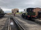
I've made a start on a second hand Agenoria Avonside 0-4-0st kit of GWR 1340 Trojan. The prototype of which is preserved at the Didcot Railway Centre.
This was one of the earlier kits where you have to laminate various etchings to make the crossheads but fortunately I have a spare pair of Agenoria cast brass crossheads supplied as with later kits. The kit also came with a set of Slater's wheels, 40:1 gears and a Mashima 14/24 motor (if my measurements are correct).
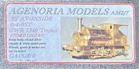
Early packaging. I wonder if the previous owner recognises it? I purchased it from the O Gauge Guild online sales site many years ago.
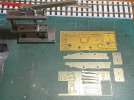
Getting stuck in to "raising rivets". My trusty GW rivet tool was red hot by the end of the day. I prefer to do all the rivet raising in one go rather than unpacking it every time I find an etch that needs treating.
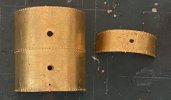
This is where I came across two etches that had been pre formed inside out! The half etch marks were on the outside of the shaped panels and it took some care to flatten them then reform with the half etched holes on the inside. The pre formed lower boiler etch had been formed correctly. I can't imagine Peter Stamper messing up, even on a Friday afternoon!
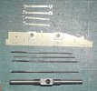
I made a start by laminating the coupling rods. I leave the excess solder on the bosses as I find these occasionally delaminate when reaming out the crankpin bearing holes and hopefully this will give them more strength. I still need to ream out with the largest of them. I also reamed out the axle bearing holes to be a tight fit on two of the bearings. The two side frames are fitted together with these bearings to align them. I will tack solder the two ends together before cleaning up the frame edges and then cutting the frames to take a set of Slater's sprung horn blocks for the leading axle.

This was one of the earlier kits where you have to laminate various etchings to make the crossheads but fortunately I have a spare pair of Agenoria cast brass crossheads supplied as with later kits. The kit also came with a set of Slater's wheels, 40:1 gears and a Mashima 14/24 motor (if my measurements are correct).

Early packaging. I wonder if the previous owner recognises it? I purchased it from the O Gauge Guild online sales site many years ago.

Getting stuck in to "raising rivets". My trusty GW rivet tool was red hot by the end of the day. I prefer to do all the rivet raising in one go rather than unpacking it every time I find an etch that needs treating.

This is where I came across two etches that had been pre formed inside out! The half etch marks were on the outside of the shaped panels and it took some care to flatten them then reform with the half etched holes on the inside. The pre formed lower boiler etch had been formed correctly. I can't imagine Peter Stamper messing up, even on a Friday afternoon!

I made a start by laminating the coupling rods. I leave the excess solder on the bosses as I find these occasionally delaminate when reaming out the crankpin bearing holes and hopefully this will give them more strength. I still need to ream out with the largest of them. I also reamed out the axle bearing holes to be a tight fit on two of the bearings. The two side frames are fitted together with these bearings to align them. I will tack solder the two ends together before cleaning up the frame edges and then cutting the frames to take a set of Slater's sprung horn blocks for the leading axle.


