Cheapo CNC Milling

Ian_C

Western Thunderer
Robin,

many years ago I had a training at milling machines and learned that you always need to work against the direction of the turning cutter. I believe the correct English technical term would be "upcut milling", in German it is "Gegenlauffräsen". This might be another reason for breaking cutters in corners.

Michael
Potentially the cause of cutter breaks into corners could be cutter loading. Depending on the geometry of the corner and the diameter of the cutter (and its run out) the cut per tooth can increase around an internal corner. Worth checking to see if you have any options for adaptive cutting that would reduce the feed rate in those areas.
 

simond

Western Thunderer
The cranks came out better than I'd have thought. I'd be interested to see how the machine copes with more complex parts, a bit more 2.5D or 3D - like (intake of breath - pause for dramatic effect.....) machined brass driving wheel centres!

I’ve got a Doosan Lynx 2100 LSYB at work, which could certainly do the job, trouble is, we don’t have CADCAM for it, so it’s manually programmed. That takes hours, as will the first several prototypes, and the several hours of machining time mean that a brass wheel is possible but not going to be cheap, unless you want hundreds...
 

JimG

Western Thunderer
The cranks came out better than I'd have thought. I'd be interested to see how the machine copes with more complex parts, a bit more 2.5D or 3D - like (intake of breath - pause for dramatic effect.....) machined brass driving wheel centres!

Ian,

Here's a thread on my milling brass loco wheel spoke centres - in 1:32 scale, but I've also done others in 1:64th/S Scale. I use brass plate since I find that's the easiest way to hold the material. I use CZ120 clock brass from Ian Cobb.

1/32 - A Loco for the Garden

I use Mach3 as a controller and I think it does a lot of path and feed controlling with cutters at corners to minimise breakage. I've certainly had no breakage problems using 0.5mm to 2mm diameter carbide slotting cutters. I do notice that the feed rate varies from the rate stipulated in the GCode file during cutting.

Jim.
 

Boyblunder

Western Thunderer
Jim, I've read through your wheel machining thread this morning - very interesting thanks. It has become clear to me that the 3018 cheapo mill won't do any serious engineering, the challenge for me is to find out what I can do with it with very little engineering knowledge. Learning to use Fusion 360 has been a slow process, chosen because in the right hands it seems to be capable of drawing anything, easily creates .stl files for the 3D printer and also creates CNC files for milling/engraving/drawing etc. I have successfully created a few plasticard and woodworking pieces, racks, boxes etc. and think the post-processor for GRBL in Fusion 360 is a bit random. It has lots of options to produce feed ramps, spirals etc. but doesn't always do what I expect and creates some very long codes when much shorter scripts would do. Here is a brief sample from a test piece, I've edited out auto-generated text about some actions not available with the free version and added a reminder to me to check the spindle speed because the 3018 doesn't accept direct spindle speed commands. The same machine was available from Gensmart with Mach3 installed and I'm wondering if that would have been an easier starting point because Fusion and Mach3 is used by people that do know what they are doing so presumably the Mach3 post processor works well.
Robin

(Square test 2)
(Gensmart Z set to 35mm Tool set to 15 O/A)
(Machine)
( vendor: Amazon)
( model: Gensmart)
( description: 3018 RMI)
(T2 D=3 CR=0 - ZMIN=-3.2 - flat end mill)
G90 G94
G17
G21
G28 G91 Z0
G90
M0 (Hold- Set spindle speed)
(2D Pocket2)
T2
S500 M3
G54
G0 X0.444 Y1.373
Z15
G1 Z5 F250
Z2.5
G2 X1.209 Y-1.373 Z2.344 I0.383 J-1.373
X0.444 Y1.373 Z2.187 I-0.383 J1.373
X1.209 Y-1.373 Z2.031 I0.383 J-1.373
X0.444 Y1.373 Z1.875 I-0.383 J1.373
X1.209 Y-1.373 Z1.718 I0.383 J-1.373
X0.444 Y1.373 Z1.562 I-0.383 J1.373
X1.209 Y-1.373 Z1.406 I0.383 J-1.373
X0.444 Y1.373 Z1.249 I-0.383 J1.373
 

Mikemill

Western Thunderer
On the subject of machining loco drivers, I built a pair of G3 LNWR Jubilee’s last year along with Mike Williams of this parish. We could not find suitable wheel castings so I have to make them, that’s eight 3.75in dia drivers.

The wheels were cut from 6mm ali plate and the tyres from 10mm slices of 100mmm dia EN1a steel bar, and yes, a lot of swarf. The centres were made from brass with quartering squares, they work very well.


Mike


P1110327.JPG
 
This thread is an interesting read. Milling at the sizes demonstrated by Giles coming from the StepCraft are what I was hoping to eventually achieve when I put some steppers on my Proxxon MF70. To translate CAD to GCODE I purchased a reasonably priced licence of EstlCAM, which for me just worked. It was the last part of the link from my line drawings to those shapes being cut. It has capability for 3D but I have not used that (yet). I found then that I need some backlash compensation or a zero backlash table. The former is not possible with the Arduino/CNC shield/GRBL/UGCS setup that I opted for. The latter is a whole bunch of work, though I did obtain a second table to have a go at it with I have not got further than looking at leadscrew nuts that I could purchase to make a start.
Hi

I started new conversation under "CAD Corner" about a simple CAM package to assist me in making up the G-Code. "Simond" suggested 2 possible programs, but then also suggested I post here, so to put all views together.

Just to clear things up, I am an Mec engineer, but other than doing drawing board design, I never did any practical work most of my working life till I started Hobby Holidays. When my Master Chassis started sell in (to me ) large numbers, I could not carry on making the parts on a 4 inch swing lathe with a milling attachment. So initially I sub-contracted all the milling work, but it was costing a fortune and suppliers were not always reliable. What would it cost for me to make the bits myself. After a lot of research, I plumped for a TORMACH PCNC1100 . It's called a bench top machine but it needs to a dame good bench at 600Kg, to support it as the table move from side to side

Now sales have basically stopped for the "Master Chassis" (Flooded the market with something that never wears out). So now I have a decent milling machine and little to make on it. I learnt how to write G-Code but it was always simple X, Y, stuff and then either mill a face or drill a hole, which is very simple in G-Code. However as soon as you put curves into the profile, I just wound up in clockwise/anti clockwise, end points mess etc etc. Especially when they are not 90 deg curves.

So I was looking for something simple to take me to the next step of using the machine to profile mill. I would have preferred some thing free as it will not earn any money. "Simond" suggested dxf2gcode and Ultimate CNC - GRBL controller. The second seemed a bit more than I wanted without it saying it specifically did what I wanted it to do. However the first sounded exactly what I wanted, but.

I downloaded it and actually managed to get some G=Code out of it. However very quickly I found 2 problems and no possible way of changing 1. The first was it put X 0 and Y 0 over 1.7M (yes 1700mm) away. You could use offsets to move the cut line/shape nearer but I was concerned that the use of offsets may limit my use later. The biggest problem is I could not find a way to change it from cutting inside the line to outside. There was no manuals that I could see. I suspect it was designed by an CNC expert for CNC experts, just have difficulty seeing that as a valid market.

So after "Simond" pointed me here I spotted the mention of "EstlCAM". I thought I would have a look today. It's not free but $59 it does not break the bank. However you can download for free and appear to use it for free. Maybe you have to pay for it, for support, or maybe there is a time limit, or possibly a max number of lines of code, I could not see anywhere it is mentioned

You can put X & Y 0 anywhere, You can change from inside to outside at a click and I got a sensible file as an output in 30 mins. So now I should be able to profile mill coupling rods inc fluting (setting the rods at 90 Deg). From what I have seen it would be easy to punch rivets. I will try to keep you informed, but my current workshop has no heating, so I tend to do research during winter.

If you want to know more please please ask, there is a lot of helpful friendly people here on WT

Regards Phil
 

simond

Western Thunderer
A bit of an “oops”. I was using my little cheapo miller to do some repeat work on the axleboxes and hornguides for the loco chassis I’m building at the moment (see my workbench for CSB chassis) and having finished the axleboxes & horns, had a work meeting, and simply left the machine on my bench, all plugged in, but not running.

I came back to it about three hours later and set up to do the next part of the suspension - the vertical bars with a hole at one end that are soldered to the axlebox and link it to the CSB wire. Much faffing with G-clamps and toolmakers’ clamps and bits of wood and V blocks, etc, finally arriving at a set up where I can drill the hole, and then mill the piece off the end of the strip, loosen the vice, slide the strip along, tighten and repeat. I jog the machine around to convince myself that my “usine a gas” won‘t crash, and hit M3 to run the spindle to drill the first hole.

it spins almost slowly enough to count the revs. Much head scratching, it seems that for whatever reason, the spindle control is now outputting 1.04V in place of the ~24V that is expected. Don’t know what has died, nor indeed, why. Hopefully one of my team at work, who understands the arcane ways of silicon, will be able to fix it. Meanwhile I ordered another controller from Amazon, so hopefully I can make it work.

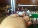
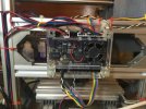
So, dismantling photos…
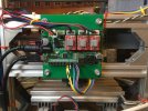
image.jpg

axis drives labelled and unplugged

image.jpg

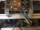
And a close-up of the axis limit switches connections.
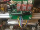
image.jpg

I believe it doesn’t matter which way the switches are connected, because it “knows” which way it’s going, but in any case,
Zen, Y & O are Z-zero, fully up
-
Yen, Bk & W are Y-zero, table fully back.
-
Xen, Bu & Gn are X-zero, head fully left
Xen, Gy & Pu are X-max, head fully right.

I have not yet fitted an emergency stop, but it connects to A0. The new board has a different connection for that, which I will set up.

I’ve been using “Universal Gcode Platform” as a controller. It’s convenient as it allows the use of a mobile phone as a cordless pendant.
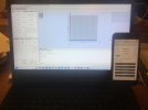
image.jpg

I’ll add the rebuild when the new controller arrives.
 

simond

Western Thunderer
Family day in that there Lunnun town, meanwhile the mighty river swung by south Kent and my new controller was delivered.

Happily the screws fit the same rail spacing so installation took all of the give minutes required to get longer screws from the garage, and do them up.

image.jpg

Then start plugging in wires…

image.jpg

In precisely the opposite order to the previous board.
 

simond

Western Thunderer
It worked. After some axis inversions and various other faffing.

I copied the settings file from the old (0.9) controller (happily I could, because the bit that had gone wrong did not affect it, but there's a moral there - copy the settings before it goes pear-shaped...) and then copied the settings from the new (1.1) and changed them to match.

I then tried to home the machine, and it crashed. Principally, the Z axis went down instead of up, which stopped the machine homing (they pull the spindle right up first in case there is a tool in a hole) and when I fixed that, it seemed that the axis mask was not right. Minor fiddling and it worked correctly. The setting $3 is 5 in the old controller, was preset to 2 in the new one, and when I set it to 5, I then had to set it back to 2. Whatever.

I have attached a PDF file that contains lots of commands and other relevant info in case anyone else has the same issues to address.

Right ho, let's see if we can cut metal...
 

Attachments

  • GRBL & G Codes.pdf
    724.7 KB · Views: 8
Top