Richard Gawler
Western Thunderer
This story begins when I bought a Marcway point ("right hand, 6ft radius") and encountered a very pronounced wheel drop using the usual fine standard wheels from Slaters. I had three goes at selling this in various places bringing absolutely no interest at all so I thought I might as well try to rebuild it to the "modified fine" or "0-MF" standard. The result looks good to me and works well so I thought I would share what I found using fold-up gauges to do the rebuild.

This is the original point.
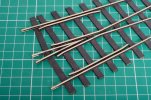
The gauge is 32 mm and the flangeways each side of the vee measure about 2.4 mm on one side and 2.6 mm on the other. The nose of the vee is hanging in mid air and not sitting on top of a timber.
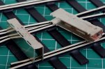
These are the two gauges for 0-MF, purchased from Roxey Mouldings.
I began the rebuild by cutting the wing rails to make them separate from the point blades. Then I took the micro flame torch to the six short lengths of rail on the point and lifted them off, one at a time. Cleaned up these bits of rail and the timbers well enough to put them back again.
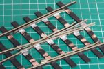
My reconstruction began by refitting the straight side of the vee to track gauge, followed by the second side of the vee and having a very good look that these were in their proper new place and truly bisecting the space between the stock rails.
What seems interesting to me is, the nose of the vee has moved a full 8 or 10 mm towards the other end of the point and ended up on top of a timber and looking a great deal better.
Then I added the wing rail on the curved side of the vee, the straight part of this rail will end up aligning with the straight point blade. The result of this also pleased me. This must be the most difficult way imaginable to build a point but with this third bit of rail in place the rest has got to follow more easily.
The second wing rail (on the straight side of the vee) is easier because you get a bit more wriggle room when you come to align the associated point blade. By wriggle room I mean from an aesthetic point of view rather than a purely mechanical one.
The two check rails followed. I used the fold-gauges to do these, but if you look at the gauges you will see they won't sit flat on the common crossing to let you do this. So I turned them around (so they were hanging in mid air until I put a bit a ply underneath them), and took the flangeway gap from the adjacent stock rail, very naughty I know and see later.
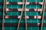
This rework was one of those modelling tasks where but I didn't really know what to expect, but when I got a result it seemed sort of sensible. The point blades are still set to 32 mm gauge and the wing rails are 31.5mm gauge - okay.
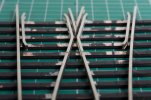
The next task was to unsolder four or five blobs of solder on each point blade, one at a time, and gradually slew the rails across to line up with the wing rails. You get about 0.1 mm each time (because you can only unsolder one blob at a time) so quite a lot of iterations needed. There is no need to remove the paint first, the heat from the iron destroys it neatly enough.
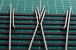
Money shot.
Definitely good enough to run a train and looks a whole lot better too.
I really am extremely pleased with my handiwork here, but applying my digital vernier I can see it isn't really "0-MF":
The etching process is always going to give an error of +/- 0.1 mm or so depending on the processor. So I'm not sure if fold-up gauges are really good enough for the job. However, I do emphasise, trying out some wagons with Slaters wheels, running is excellent.

This is the original point.

The gauge is 32 mm and the flangeways each side of the vee measure about 2.4 mm on one side and 2.6 mm on the other. The nose of the vee is hanging in mid air and not sitting on top of a timber.

These are the two gauges for 0-MF, purchased from Roxey Mouldings.
I began the rebuild by cutting the wing rails to make them separate from the point blades. Then I took the micro flame torch to the six short lengths of rail on the point and lifted them off, one at a time. Cleaned up these bits of rail and the timbers well enough to put them back again.

My reconstruction began by refitting the straight side of the vee to track gauge, followed by the second side of the vee and having a very good look that these were in their proper new place and truly bisecting the space between the stock rails.
What seems interesting to me is, the nose of the vee has moved a full 8 or 10 mm towards the other end of the point and ended up on top of a timber and looking a great deal better.
Then I added the wing rail on the curved side of the vee, the straight part of this rail will end up aligning with the straight point blade. The result of this also pleased me. This must be the most difficult way imaginable to build a point but with this third bit of rail in place the rest has got to follow more easily.
The second wing rail (on the straight side of the vee) is easier because you get a bit more wriggle room when you come to align the associated point blade. By wriggle room I mean from an aesthetic point of view rather than a purely mechanical one.
The two check rails followed. I used the fold-gauges to do these, but if you look at the gauges you will see they won't sit flat on the common crossing to let you do this. So I turned them around (so they were hanging in mid air until I put a bit a ply underneath them), and took the flangeway gap from the adjacent stock rail, very naughty I know and see later.

This rework was one of those modelling tasks where but I didn't really know what to expect, but when I got a result it seemed sort of sensible. The point blades are still set to 32 mm gauge and the wing rails are 31.5mm gauge - okay.

The next task was to unsolder four or five blobs of solder on each point blade, one at a time, and gradually slew the rails across to line up with the wing rails. You get about 0.1 mm each time (because you can only unsolder one blob at a time) so quite a lot of iterations needed. There is no need to remove the paint first, the heat from the iron destroys it neatly enough.

Money shot.
Definitely good enough to run a train and looks a whole lot better too.
I really am extremely pleased with my handiwork here, but applying my digital vernier I can see it isn't really "0-MF":
- The flangeways at the common crossing measure 1.4 mm not the 1.5 maximum expected (okay)
- The check gauge measures (as well as I can manage) 29.9 mm not the 30.0 mm minimum expected (does not meet the standard)
- The flangeways at the check rails measure 1.3 mm
The etching process is always going to give an error of +/- 0.1 mm or so depending on the processor. So I'm not sure if fold-up gauges are really good enough for the job. However, I do emphasise, trying out some wagons with Slaters wheels, running is excellent.
Last edited:
