Breaking Ground - Finescale - of a sort

simond

Western Thunderer
The scrubbing effect of the steeper angles between the the rail head and tread centrelines act as an extremely effective brake force, and the tendency to "kick out" only occurs when the tender or wagons are under load.

Sorry, Pete, might be me but I can’t visualise what you‘re saying here. Can we have a sketch?

cheers
Simon
 

Peter Insole

Western Thunderer
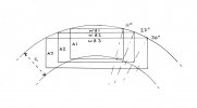
No problem Simon. Here is the requested sketch:

The proportions are grossly exaggerated, but I hope that, along with the following descriptions it will help to explain what I mean?!

hhzpoint 028.jpg

I have shown three different rectangles, representing rigid wheelbases, (WB1, 2 and 3) while the corresponding vertical sides (A1, 2 and 3) are the axles. The axles are (obviously!) drawn to the same gauge as (G).

The drawing has been made on the assumption that the wheel rotational centre points are directly over the outer rail head.

Although the relative angles of the rotating wheels at the point where they meet the centre line of the curved, outer running rail head has only been measured with a simple, plastic protractor - I hope it nonetheless demonstrates that the rotating wheels are actually "skidding" by increasing degree; in this case the difference between 11, 22 and 30 degrees!

I haven't bothered to measure the angles on the inner rail, but I think it should be fairly obvious that even though there is a considerable discrepancy with the wheel/axle centres that are way off line, the relative angles will nonetheless be notably greater.

Gauge widening in this particular exercise, where the use of flat profile wheels - where the tendency is to run outwards as far as the flanges allow, could disastrously (?) increase the distance from the wheel/axle centre points even more.

While I am aware that coned treads will naturally introduce an element of equalisation over the inner and outer rail centres, by implication, that simply proves that both wheels will then be running off-centre by degree, on any curve, however slight that may be - and will still be "skidding" in the process!

Although I tried my best to be careful with gauge issues during construction, clearly, my main problem stems from a simple issue of excess friction!

Pete.
 

Genghis

Western Thunderer
Coning is what gives railway wheelsets stability. On straight track it results in the wheelsets precessing, controlled by the primary suspension. On curves it compensates for the outer wheel having farther to travel than the inner wheel: by having a larger effective radius on the outer wheel you significantly reduce the imbalance. With cylindrical wheels formed from material that has a high friction you run the risk of derailment by flange climbing - likely to be increased if you radius the flange without coning the wheels.

Rail wheels are usually coned at either 1:20 (eg UK and France ) or 1:40 (eg Germany and USA) and the rails are inclined at the same angle. Given your very tight radius curves I would be inclined to use 1:20 (or even 1:10 but that might result in hunting on straights).

David
 

Brian McKenzie

Western Thunderer
I'm thinking that the inside face of Peter's flanges may need to be at a greater angle so that the outer edge of them does not bite into the top of the rail head at the tight curvature, and then climb over. This is easier to visualise when realising that his axles are somewhat off being perpendicular to the curved rail.
I suspect that the tip, or the outer edge of the flanges is making first contact with the rail, rather than any root radius between tread and flange.
Only two wheels would need modification to test this theory.

-Brian McK.
 

simond

Western Thunderer
Cheers Pete.

Started typing, just seen Brian beat me to it: where the angle between the tangent to the rail, and the axle, is so far from 90 degrees, I think that the tips of the flanges must rubbing on the inside of the rail, which is an effective brake, particularly in a pushing situation, whereas pulling the vehicle will tend to bring the outer wheels away from the rail.

I don’t think the differential effect of coning is relevant here, as I believe your trailing wheels are all free to rotate on their axles - I’m sure it matters with your loco, however, particularly with such a tight curve.

David,

I don’t understand why flange climbing is more likely with a cylindrical wheel. Is it simply because the flange is not guided away from the rail? And would a generous fillet radius between tread and flange not help?

atb
Simon
 

Peter Insole

Western Thunderer
Thank you David, Brian and Simon for your most welcome replies. You are all quite right of course! No amount of coning will alter the effect described, where wheels of all vehicles rotate on an axis which will always be at odds with that of any curved rail.

This particular problem is what I believe Cleminson and Heywood, among others, attempted to address, but the roughly similar solutions effectively required a third axle in order to achieve it!
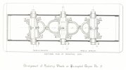
hhDBhey_plate21b heywood.jpg


Properly profiled and coned steel wheels would be the most desirable, let alone obvious choice! The problem for me is both the eyewatering cost of equipping our stock with same, and not having a lathe (or experience operating one) or other appropriate tools in order to set any up to our peculiar gauge!

The Horwich, 18 inch gauge railway is what I am basing ours on, where only the locomotive had coned wheels - while all other stock had flat profile, free running wheels on fixed axles.
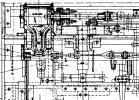

horwichwren z18inch locos 562 SCALED TO PRINT.jpg

Incidentally, according to my copies of drawings that I have scaled to permit conversion to 5 inch gauge (as above) - the loco wheel profiles and proportions are pretty much spot on for 7.25 gauge - while the plastic ones presently fitted to our engine could be replaced with 7.25NG profile, without having to adjust any of my permanent way!

The terribly tight "Top curve" is also (surprisingly) to prototype scale at 5inch gauge for the 13ft radius of the Horwich system!

I have measured and noted that both the locomotive and tender (driving truck) have a 9 inch wheelbase, which just about goes round, the coal wagons at 10 inches do not at all when under any sort of load, while the bogies - at 5 inches positively sail round with almost zero resistance!

The original Horwich wagons (common) had a wheelbase that scales down to 7 and 9/16 of an inch!

I will have much more play (er, experimentation) with this in the coming weeks... but I will not let it get on top of me. There is so much else to be getting on with before I can snip a ribbon or crack open a bubbly bottle!

Pete.

P.S. Simon is right, that when the loco is pulling, the flanges do get pulled away from the rail in between the loco and tender, but I am still not sure that is the primary cause? Flange contact is full, and at risk of "climbing" at the leading axle - and that, so far, has not happened - nor shown any sign of - thus leading me back to the suspicion that the causes are probably multiple - a combination of too much friction, wagon flanges digging in (though not sufficiently to climb, but adding to the brake effect) and a drawbar issue?!
 

Genghis

Western Thunderer
I don’t understand why flange climbing is more likely with a cylindrical wheel. Is it simply because the flange is not guided away from the rail? And would a generous fillet radius between tread and flange not help?
With a cylindrical wheel you are bound to get the flange running hard against the outer rail. If the friction coefficient is high then that will allow climbing.

I hadn't spotted that the wheels are independent - that negates the differential travel distance problem but means that the self steering action is also compromised. Probably not an issue here. I'll get back in my box!
 

Osgood

Western Thunderer
The good thing about all this is there is plenty of thickness on those nylon wheel flanges to allow a nice shallow angle on the flange.
And if anyone can sort this issue, Cartazzi Pete can.....
 

simond

Western Thunderer
With a cylindrical wheel you are bound to get the flange running hard against the outer rail. If the friction coefficient is high then that will allow climbing.

I hadn't spotted that the wheels are independent - that negates the differential travel distance problem but means that the self steering action is also compromised. Probably not an issue here. I'll get back in my box!
Thanks David, that is what I had concluded.

What are your thoughts about the root radius? I think a sufficient angle on the flanges to prevent flange/rail contact, and a generous root radius will help here.

atb
Simon
 

mickoo

Western Thunderer
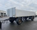
It all seems very complicated and maybe overly so, can you just not make the leading axle of the tender/truck/ vehicle of choice rotate like a drawbar trailer, very common in Europe, quite rare in the UK.

Not sure how it would perform when being pushed, maybe a tendency to jack knife, but pulling it'd release an awful lot of stress and drag.

I do agree with the flange being tapered comments, that should be the first course of action at a bare minimum.

Image.jpg
 

Osgood

Western Thunderer
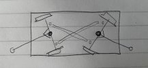
That would solve 1/2 the issue Mick - to fully solve it would require both axles to pivot, connected by a crossed pair of tie rods :)

IMG_5779.JPG
 

simond

Western Thunderer
Tony,

An anti-parallel mechanism takes us back to the LUL steerable bogie project, with which I was involved as a young engineer at Lucas Girling, way back in the mid 80’s. It only works if its coupled fore and aft (or there are bogies on a longer vehicle). Otherwise the trailing axle is missing a constraint. I that is resolved, it works well, I understand. Pete can convert all his stock to bogie…

Mick,

your trailer helps if its being pulled, but Pete’s issue is pushing, and I don’t think it would be of any benefit for that.

atb
Simon
 

simond

Western Thunderer
Mentioning Lucas (prince of darkness) Girling reminds me of a couple of “oops” which still make me giggle.

they‘d commissioned some lovely cast brass paperweights, a sort of oval projection map of the world, with words around the outside “Lucas Girling, in action around the world”. I think it was all caps. They missed the gap between “in” and “action”…

some time later, I was working in the car brake development team, we advertised for engineers and technicians to join us. “join Lucas Girling, leaders in breaking technology”. I’m sure they meant “braking”, but out of the mouths, etc…
 

Osgood

Western Thunderer
Not sure I follow Simon - the trailing axle (say left on diagram) is restrained by three points of contact (ah - sailing days :)) ) which are:
axle centre pivot, right hand tie rod, left hand tie rod.
The mechanism is kept in check by the coupling bar on right hand axle, whose movement is constrained by the truck coupled to it.
A simpler version can be found in the AWD Multidrive semi-trailer system.
Apart from the odd marble, what am I missing?

Hopefully meanwhile Cartazzi Pete will have been furiously turning tapers on wheel flanges, which will render this huge hole we are digging obsolete :D
 
Last edited:

simond

Western Thunderer
I remember the Multidrive, I was working at Dana Spicer in those days. I didn’t get the contract :(

on reflection, I think I’m mistaken. If the front axle is constrained (by the towbar) the rear must also be.

atb
Simon
 

mickoo

Western Thunderer
That would solve 1/2 the issue Mick - to fully solve it would require both axles to pivot, connected by a crossed pair of tie rods :)

View attachment 187627
I don't think that would work because at some point one of the draw bars will be straight, or at the least a different angle as the stock enters and leaves the curve.
 

Peter Insole

Western Thunderer
What can I possibly add to all this wonderful stuff, except thank you so much to everyone who has contributed to such a fascinating debate!

With so much to think about, I ran away yesterday and spent a happy time playing with Rich and the kids at the East Anglia Transport Museum!

hhSAM_8548.JPG
hhSAM_8561.JPG

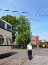
Rich, as a newly qualified PCV driver was particularly interested in the trolleybuses, especially as he has already had a go with some of the latest battery/electric vehicles that are just coming into service at Cambridge. I have been teasing him that he is a trolley driver now, except that he doesn't have to worry about staying under the wires!

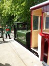
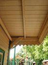
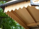
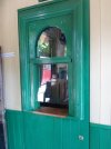
I paid a great deal more attention to the narrow gauge railway, gaining some inspiration around the station buildings in the process...

hhSAM_8546.JPGhhSAM_8554.JPGhhSAM_8547.JPG

But I must confess that it was the TRAMS that had me really thinking...!

hhSAM_8562.JPG

Oh dear, I have a horrible feeling where this could be leading...

:rolleyes:

Pete.
 

Peter Insole

Western Thunderer
Donning my sensible hat again - no, please, don't laugh - the focus has shifted back to the onerous task of shifting half a ton of topsoil!

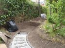
Mr. O., had a day off work today, but seemed to be otherwise occupied, apart from offering to have a quick whizz with his wonderful electric hedge strimmer, to clear some of the deeply tangled foliage engulfing the boundary fence! I was both extremely grateful for his effort, and rather horrified at the same time. The wire netting is being pushed inwards by all the brambles and other debris, and is bulging far further than I had assumed. When the baseline was finally revealed, I found that I have notably more ground to play with than I first thought.

hhSAM_8571.JPG

When calculating the maximum curve, I had made some allowance for all the nasty, prickly and snagging stuff... but by rather too much it would now seem.

I got the template out of the shed and laid it down over the newly cleared soil, in order to mark the exact point of the curve run-off... and that is where it finally dawned on me...

It is no good, before I go any further, I am just going to have to accept the inevitable... get back down on my knees... lift it all up... and ease that wicked radius!

Keeping the soil at a shallow angle in the cutting under the fence will not be needed if I set some gravel boards in - or even build a dwarf wall to hold the ground back? OK., so it will be quite a lot of extra work, but at least lifting the ballast and jiggling the pavers will not be quite as bad as having to start completely from scratch in previously undisturbed and compacted ground...?!

Pete.
 
Top