18 inch gauge shunting engine

michael mott

Western Thunderer
While waiting for Simon to go crawling under a carriage at SVR to look at the intricacies of the braking system for me , I have returned to an old project that is close to Peter Insoles heart. The Horwich shunting engines.
This also gave me the opportunity to clean up the workshop and put the drawings I have up on the wall.
IMG_5119x1024.jpg

IMG_5116x1024.jpg

about 4 years ago I purchased from the NRM 5 drawings of the Horwich shunting Engines including the following drawing numbers
3436 coloured rendering of general arrangement without saddle tank
3869 full size wheel bearing
3870 full size hornblock
3879 frame and boiler
6749 general arrangement showing the saddle tank
I am using these drawings to prepare a 2D cad set of drawings with all the major areas on separate named layers Full size in order to avoid the sorts of confusions that are encountered with old stacked drawings of our subjects.
I am a bit old school in that I only have Auto-cad Lt 2000 but it is more than sufficient for my needs, and I am not prepared to go through the 3D learning curve.
As part of my discussions with the members on Peter Insole's thread "Finescale of a sort" there are all sorts of hidden gems, not all accurate in these old drawings, I say this with all due respect having learned how to draw with a board and T square.
Being as these drawings are drawn and printed and Digitized By the NRM at 3 inches to the foot scale and I have both versions, it is still very time consuming and often having to resort to laying the scale ruler (taboo) over the print to confirm or extrapolate a given dimension that is suspect.
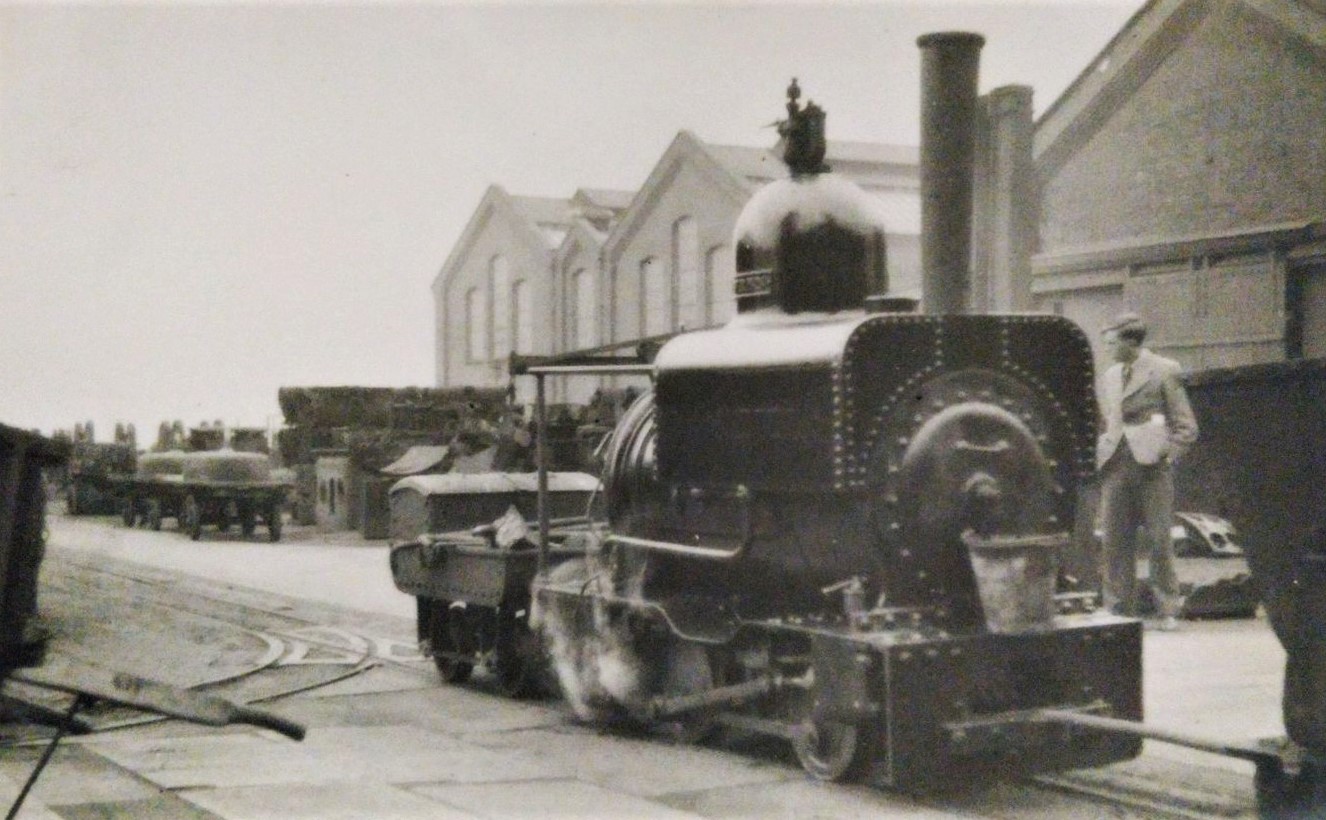
That said I am enjoying the process of detection and will hopefully eventually to have a complete set of all the components of the little shunting engines that worked so hard at Horwich in very important roles as aids to building the large standard gauge locomotives, shifting and carrying parts around the plant.

I have already partially built models of these locos in different scales, working from these old drawings plus the ones that were drawn by Roy C Link for the model community. these were made by constantly converting scales and dimensions, and making compromises regarding gauges.
I will put up a thread about the little Horwich locos in the appropriate area. with the background models already in existence, my plan is also to build another model to the scale of 3/4 inch to the foot so the gauge will be set to 1 1/8th inches I am not going to conflate the imperial and Si (metric) systems Which has been fostered on the model railway community for decades, I think in UK imperial units was taught them that way in school and the data that I have to hand is drawn in those same units.
Once the drawings are done, they will be able to be manipulated into any scale or system using the tools we now have in our hands, and it is so much easier not having to convert the numbers as I am drawing.

Michael
 

Peter Insole

Western Thunderer
Michael, the NRM drawings of which you have copies seem to be pretty much all there is available! I have found that there are some parts on those G/A's that are vague and others (by omissions) misleading, so if you get puzzled or stuck with any details do say so!

I have a small collection of photographs by Tom and myself taken on two separate visits to inspect "Wren" at York. Unfortunately, I have not had the opportunity to do the same with (the marginally more original) "Dot" at Tywyn. Ordinarily, I would need little excuse to hop in the motor and head off to that part of the world, and indeed did that trip quite regularly in former times, but I am rather more travel restricted now!

It must be borne in mind that both loco's have been modified during their years of service, and that Wren is in a particularly poor condition - as well as having been botched by some previously well-meaning, but sadly careless restorers!

I will do what I can to help untangle any mysteries, based on what I have discovered so far though.

Pete.
 

michael mott

Western Thunderer
Pete, thank you for your interest and offer. so here is my first question, in all the photographs of the locos that were built at Horwich they show a different front "buffer without the hooking bar and just a differently shaped bit of Iron with a hole. did you measure up it?

I can only access this computer in the house and not in the workshop so the reason for the delays sometimes re posts.

Michael
 

michael mott

Western Thunderer
Hi Pete,
Second question, do you have a photo of the top spring ? The drawing 6749 claims there are 7 plates 1plate 5/16ths and 6 plates 1/4 inch. The drawing shows the top plate as if the end eyes or loops for the hangers are solid with holes drilled through.
I am going to guess that these are in fact looped like the one on the left, to form the eye. Can you confirm.
IMG_0809x1024.jpg

Thanks
Michael
 
Last edited:

Peter Insole

Western Thunderer
Michael, there were three slightly different designs of headstock, depending on build batch, with two arrangements of rivet/bolt holes!

Styles listed in order of build, with notes for each below image:

horwichwren 3b2 Dot HWR_1899a NOTE headstock eye casting + drawbar.jpg

Beyer Peacock "Dot" - first order number, but last delivered of the original trio. Note: This image is the only interim one showing the later "socket" style coupler, but oddly with the original drawbar still fitted!

horwichwren 15c 9th August 1953 SRA130126_neg1410-XL NOTE point levers hanging on reverser qua...jpg

Beyer Peacock "Robin" and "Wren" - remainder of first batch. Note distinct, inverted T cut-out above revised coupler. This design matches the (other) "Dot" that was retained by Beyer Peacock. Also note that this particular pattern, although original, does not appear on any of the G/A drawings.

horwichwren 10b Wasp c1950.jpghorwichwren 2d Midget large_DS110136a.jpg

Horwich "Wasp" and "Fly", then "Mouse and "Midget" - The home builds. Different arrangement of bolts/rivets and rectangular cut-out with 90 degree corners (pattern shown on drawing of loco with saddle tank). Motion guards were fitted to all four (as shown on drawings) but removed again after short while in service. Additional line of rivets and angle remained along bottom of headstocks.

Evidence clearly suggests that the motion guards shown in the drawings were removed before the engines were rebuilt with saddle tanks!

There are no surviving photo's or any other records showing "Bee" - the last one built, so it impossible to tell what configurations it carried.

I'm afraid that I had already started building my loco some time before the opportunity arose to examine "Wren", so I did not take any measurements. I had already noted that the outer of each pair of attachment bolts on either side of the revised, cast iron "pocket" coupler used the holes of the original buffing plate, so extrapolated the dimensions from that.

The new coupler depth is the same as the original too, but please note that it does not have the support section underneath (as depicted in the drawing!).
In both cases, the cast iron buffer/couplers were fitted over timber pads (not clear on the drawings). The originals were T shaped to accommodate the support section.

There is no surviving evidence to suggest that any of the original buffing plates were still fitted after all the engines were rebuilt with saddle tanks - although the image of "Dot", still carrying a drawbar is a slightly odd arrangement?!

The original drawbar was probably regarded as an absolute pain by the enginemen, and may well have been a source of complaint - It would certainly have got in the way when having to reach with a crooked arm, right down under the steam chest to open the single drain cock?!

Hope I have not missed anything?

Pete.
 

michael mott

Western Thunderer
Pete, thank you for your detailed answer, I can see that I am going to be busy asking you questions. I did note that the drawings were calling for rivets on the front steel plate and yet have only seen pictures with bolts.

Michael
 

Peter Insole

Western Thunderer
Hi Michael,

On most heavy-duty leaf springs, the top plate was supposed to be thicker than the rest. This is a detail most frequently overlooked by model makers and manufacturers! I did do that thicker top plate on my engine, but baulked at trying to emulate the nicely forged appearance of the original!!

They should indeed be solid and have teardrop shaped ends in profile - rather than simply rolled over tabs!

The only images I can find barely show part of the shape of the shackles - as I was busily concentrating on trying to descramble the Allan straight link motion without getting embarrassingly and rather publicly stuck in the confined space!

hzrpsSAM_3128.JPGhzrpvgSAM_3037.JPG

By the way, don't be fooled later by the two copper pipes in the foreground on the lower image - they are nothing to do with the original, but were for axlebox lubrication, and only fitted to by British Railways to "Wren" in around 1953.

Pete.
 

michael mott

Western Thunderer
Hi Pete.
Again many thanks for these pictures and information, so now i can delete the loop on the left and mirror the one on the right on my drawing. It is tough being so far away from these locos and the museums, My next trip hopefully not too far into the future NRM is on by bucket list of places to visit.

Michael
 

Peter Insole

Western Thunderer
Hi Michael,

They may well have had rivets to start with - which frankly strikes me as an utterly bonkers idea - and is proof positive that nothing changes very much! How many motor cars over the years were clearly designed only with convenience of production in mind, and never a thought given to all the miserable so-and-so's who soon discover that the entire engine has to be taken out just to reach and undo a simple, single but essential screw?!

Likewise, back in 1887! The headstocks would have to come off every time the cylinder bores or the slide valves required inspection, let alone any repairs!

Regards,

Pete.
 

Renovater

Western Thunderer
Michael. Look forward to following this thread with interest. Colin.

cjh17510.jpg


cjh_1810.png
 
Last edited:

Peter Insole

Western Thunderer
Thanks for posting that nice image of "Wren" Renovater, I have not seen that one before.

It is unusual as it shows the engine in a really clean condition, wearing plain LMS/BR black, but probably not long before its final overhaul. The tyres look quite thin, but are not yet minimal in this view though.

Incidentally, the image also shows one of the Horwich systems standard cast iron points with the incredibly tight (13ft radius) curve leading off! That sort of radii was no problem for any of the rolling stock, as all had free wheels on fixed axles, but the locos were of conventional arrangement. I bet there was an awful lot of grinding and teeth jarring squeals going on round there in the heyday of the system! A need to accommodate excessive wear and the consequently frequent re-profiling certainly explains why they were fitted with quite generous tyres when new. Some photos show the engines running with seriously burred over rims, and one shot even reveals curved shards starting to break away!

Pete.
 

michael mott

Western Thunderer
Have been working away sorting out both the drawing proper and also a search for suitable way to power the 3/4 inch scale model.

So far I have drawn up 4 different sets of motors and gears with the object of keeping the motor out of sight but easily accessible, and using some combination of all the brass and plastic gears I have collected over the years. The great thing about our ability to draw with the computer is being able to add layers that can be turned on and off The following drawing feels about as clean a gear train as I can with the stuff I have on hand. There is no point in salvaging this stuff if one never uses any of it.
This drawing layer is the latest one is showing a coreless 12v motor from some device that was dissembled plus a stack of plastic spur gears from a HP printer the worm and worm gear are from Kemtron many moons ago. It was an interesting exercise changing all the bits to a 16 times larger size in order to fit them into the full size drawings. These little plastic gears blown up to around 4 inches in diameter The motor is offset to allow for the stack of gears to fit between the valve rods on the model and to be as discrete as possible.

model gearing x1024.jpg I will add pictures of the gears and motor on the model build thread

Michael
 

Peter Insole

Western Thunderer
Michael, you need not worry too much about what might be visible under the boiler and between the frames in the area of the leaf springs when the loco is assembled!

The space is so restricted that on the prototype, even a slight degree of deflection in service of those springs made contact and wore holes in the boiler cladding sheets!

hzrpsSAM_3128.JPG

Returning to the image previously posted, you can see an indented repair patch fitted just above one of the spring shackles.

I would venture to suggest that even the valve rods themselves will be quite impossible to view down there anyway - Indeed, I was relieved to find that I certainly didn't have to be too concerned about any non-scale structures in that particular location, even at the very much larger scale I am working to!

Regards,

Pete.
 

Peter Insole

Western Thunderer
I forgot to mention that the same thing very much applies at the rear end as well - and I can confirm that the only practical access to the valve gear eccentrics for regular lubrication was via the lifting trap door in the footplate below the firehole!

Even then, the loco would have to have been moved forward or reversed by a few feet in order to reach all points.

Pete.
 
Last edited:

michael mott

Western Thunderer
Pete, thanks for your observations they are most helpful, I just wish I were close enough to visit the NRM and look at the loco in person. I hear what you are saying about being able to see much of the locos gear between the frames. I do have quite a few photographs that were taken for me by one of the members of another forum back when I was building the first little loco on the "Percy" chassis. and also of the other little 18 inch loco "Pet" that worked the Crewe system.

Michael
 

Peter Insole

Western Thunderer
I will do whatever I can, but even though I live in the same small country, getting to see Wren and Dot these days is not quite so straightforward for me either!

It seems like I will have to ask very nicely if someone is heading in the Tywyn direction if they would mind popping in and squeezing behind Dot to let me know whether the steam brake lever and handle is made of steel or bronze?!

Pete.
 

Lancastrian

Western Thunderer
Michael/Peter,

Drawing list for the 18"Gauge engines.

13 3436 Pipe & rod – 18” shunting engine 26/7/1887 Beyer, Peacock & Co drawing (copy of 41302)
13 3593 Axle box for 18” trolly 14/7/1889
13 3617 Wheel for 18” shunting engine 15/09/16
13 3866 Cylinders 5” dia. X 6” stroke – 18” shunting engine No date
13 3867 Valve spindle, cylinder bolts & studs – 18” shunting engine No date
13 3868 Axle, piston, piston rod, etc.- 18” shunting engine No date
13 3869 Axle box – shunting engine 7/11/1889
13 3870 Driving & trailing hornblock – 18” shunting engine 27/11/1889
13 3872 Reversing shaft & bracket – 18” shunting engine No date
13 3873 Reversing handle, rod &details – 18” shunting engine No date
13 3874 Slide bars, crosshead, & bracket – 18” shunting engine No date
13 3875 Valve rod & crosshead, lifting & swing links, quadrant, blocks & eccentric rod – 18” shunting engine 9/12/1889
13 3876 Connecting & coupling rods – 18” shunting engine No date
13 3877 Eccentric sheare & straps – 18” shunting engine 27/12/1889
13 3878 Clevis pins etc. – 18” shunting engine No date
13 3879 General Arrangement of frames, water tanks etc. – 18” gauge shunting engine No date
13 3880 Front & hind spring links – 18” shunting engine No date
13 3881 Front & hind draw-bar – 18” shunting engine No date
13 3882 Cast iron buffer block – 18” shunting engine No date
13 3884 Regulator & steam pipe – 18” shunting engine No date
13 3885 Whistle, safety valve & regulator pieces – 18” shunting engine No date
13 3886 Safety valve – 18” shunting engine No date
13 3887 Regulator stuffing box – 18” shunting engine No date
13 3888 Cast iron chimney base – 18” shunting engine No date
13 3889 Exhaust pipe – 18” shunting engine No date
13 3890 Details of smokebox etc. – 18” shunting engine No date
13 3891 Brake shaft, carrier & rods – 18” shunting engine No date
13 3892 Brake cylinder & brake block – 18” shunting engine No date
13 3894 General Arrangement of boiler back plate fittings – 18” shunting engine No date
13 3895 General Arrangement of regulator, steam brake & clack box – 18” shunting engine No date 13 3896 Firebox door & shield - 18” shunting engine No date
13 3897 Ash pit door – carrier for brick arch & firebars – 18” shunting engine. No date
13 3898 Detail of nuts, bolts etc. – 18” shunting engine No date
13 3930 No title No date Only the right hand side of drawing
13 4084 Cast steel dome – 18” gauge shunting engine N0 date
13 4351 Method of fastening 26lb. Rails to sleepers – 18” tramway 4/7/1891
13 4504 Clothing, firebox fittings & pipe arrangement – 18” shunting engine 28/8/1891
13 5258 A W. iron bogie truck – 18” tramway No date
13 5281 A Loco. Boiler trolley 18” tramway No date
13 5288 Tip truck for 18” tramway 23/7/1888 Cancelled see new tracing same number

13 5288 A Scrap skip ( trucks for 18” tramway ) No date
13 6749 General Arrangement of engine – 18” shunting engine 18/12/1897
13 9068 Two & three way points for 18” tramway 21/09/05
13 14756 Scrap skip ( trucks for 18” tramways 30/09/18 This cancels 2861
13 18885 Shafts, wheels & bearings for 18” tramway bogies Horwich works 01/06/26

13 A 5231 Trucks for 18” tramway No date

139 3871 Motion arrangement for 18" gauge shunting engine No date
139 3883 Boiler, firebox, smokebox, chimney & dome, 18" gauge shunting tank engine No date
139 6664 Saddle tank - 18" gauge shunting engine 8/9/1899, part copy, 2 copies
139 19620 Horwich fixed seating - Ross type safety valve No date

Ian
 

Peter Insole

Western Thunderer
Sorry Michael, I'm bombing your thread, but I would like to thank Ian for taking the trouble to transcribe that superb list!

Personally, I could have done with quite a few of those drawings early on in my own build. It is interesting to note that the saddle tank drawing is dated 1899, and that lends some credence to the theory that "Mouse", "Midget" and "Bee" (the latter of 1902) may have been built with them from new.

I wonder if the backhead fittings (13 3894) or clothing, firebox fittings and pipe arrangements (13 4504) might show the original pattern of gauge glass protectors in more essential detail?

Pete.

Edit; Yes I typed the last date wrong by one important digit - it should have read; (the latter of 1901)!
 
Last edited:
Top