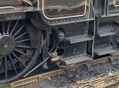
7mm Mickoo's Commercial Workbench

7mmMick

Western Thunderer
I imagine there should be a substantial bracket from the frames to support the injector body (and exhaust injector), or is the live steam injector mounted from the cab steps? Injectors definitely don't hang from the pipework.
Dave.
It’s hung in that way to give the illusion of being mounted to the rear steps to aid body removal and pipes disappearing between the frames etc. The exhaust steam injector is hung on a hefty bracket, which is unseen on the picture :thumbs:
 

mickoo

Western Thunderer
I imagine there should be a substantial bracket from the frames to support the injector body (and exhaust injector), or is the live steam injector mounted from the cab steps? Injectors definitely don't hang from the pipework.
Dave.
There is, it's the same bracket that holds the sand boxes.
 

mickoo

Western Thunderer
I’m not 100% my sandbox mounting is right to be honest. The instructions weren’t mega clear and I struggled to find prototype info. The injector pipe runs are best guess without a drawing to work from
I struggled too, spent ages pouring over photos trying to work out how the hell the sand boxes fit, problem is, I think the bracket is for earlier engines where the sand box was mounted hard up under the cab floor and had fillers in the cab. The instructions note the fillers but not why or lot had them.

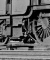
Here's a tiny crop from Rail Photoprints, the outside flat face is just above the middle step and hard up against the inside of the step hanging plate, it's also pretty much in line with the driving axles, mine are too low so need moving up at some point.

Image.jpg

I've got a GA for a 4900 class, sand box is tucked up under cab floor and the step brackets match the kit, sadly said GA shows no or little pipe runs. Drawings are pretty much crap anyway, very few pipes on the North British B1 drawings matched the one we crawled under and I've seen several different runs on Bulleid Pacifics, it's copper pipe, small short runs tend to be bent it where it needs to go and sod the drawings.

The bogie spring wire/side control seems to be working fine, I bent it in an upward arc to give downward pressure, seems to be okay but will probably need another spring in there as well like you note.
 
Last edited:

7mmMick

Western Thunderer
That’s a handy little photo crop and timely as I’m on with a JLTRT Hall and I can get these ones in the right place :thumbs: An instruction amendment maybe in order pal
 

mickoo

Western Thunderer
That’s a handy little photo crop and timely as I’m on with a JLTRT Hall and I can get these ones in the right place :thumbs: An instruction amendment maybe in order pal
You better check your prototype and date, over 300 engines and several lots so there may be batches with sand boxes in different locations.
 

SimonT

Western Thunderer
The F7 kit only covers Nos 4901-5920 and 4900ish. These locos were buitl in three lots. The first lot (254) was built over three years and compised 80 locos. Lot 268 built 4981-99 & 5900, Lot 275 comprised 5901-20. I've never seen a point described where the sandboxes moved to 'behind the rear step' and I have seen one photo taken late on where the sandboxes were still under the cab floor.

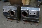
This photo of the sandboxes came from the Hagley Hall rebuild web site/blog and, for information, will show how they were mounted.
Sandboxes.jpeg

The two bolt holes are for the hanging plate attachment and the rear flange for the frame attachment. I'm not aware of any suitable drawing in the public domain. The design of our models won't help with this or the injector mountings - frames in the wrong place, hanging plates and steps being part of some removable body. Your remarks about the fidelity of the F7 kit have already been designed into the new chassis for the Hall which I hope we can get out when the COVID chaos clears.

Perhaps Graham or Dave might have some better ideas.
Simon
 

mickoo

Western Thunderer
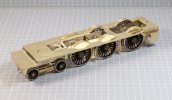
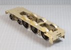
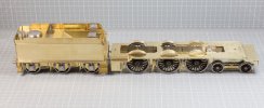
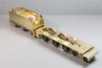
Completing the base footplate is always a nice milestone I think, it's when the model starts to look like an engine, it also shows if the frame is level and just as importantly, that the tender footplate levels up against the engine.
Happily everything here hit the home run right out of the blocks.

I've changed a the way the lamp irons fit, the kit is designed to have them fold up from the main sheet underneath the overlay and I've found it hard to then clean the cusp of the stems, in addition they become prime targets for being bent and knocked. The fold up stems were snapped off and the recess in the base sheet left blank. Toward the end I'll dress nice smooth straight ones, put a bend in the base and push up through the slots in the upper detail overlay, the bent tab will then sit in the recess left over from the fold up ones.

Not having a half etch bend line the new lamp irons stems won't have that inherent weak point any more, yes you can fill that slot by flooding it with solder, but solder is still a frangible point and weaker then a full thickness brass bent stem; that's my reasoning behind it all

The engine will be 6952 so we're going to need to make a few more changes elsewhere which I'll show along the way.

Briefly back to the sand boxes, they were indeed mounted too low and now that I have the steps as a reference, can be refitted at the correct height.

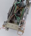
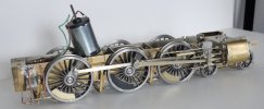
IMG_10758.jpg

IMG_10759.jpg

IMG_10761.jpg

IMG_10763.jpg
 

SimonT

Western Thunderer
The injector is a preservation change. For Swindon authenticity, the live steam injector should be only on the right and further back. The exhaust steam injector should lurking in the gloom almost at the bottom of the frames.

Edit: Of course, I should add that exhaust steam injectors are from the world of express pasenger engines. Plain Jane goods engines were better served by two live steam injectors. I suspect the 47s were the exception to this rule but they were hadly Plain Jane.
 
Last edited:

Dog Star

Western Thunderer
Of course, I should add that exhaust steam injectors are from the world of express pasenger engines. Plain Jane goods engines were better served by two live steam injectors. I suspect the 47s were the exception to this rule but they were hadly Plain Jane.
The GWR 2800 and 2884 classes carried exhaust steam injectors although not in the gloom, those fittings are out in the limelight!
 

Dave Holt

Western Thunderer
The Romans, what did they ever do for us, heh!;)
Good question.
I know the GWR generally refused to modernise their ideas to include high degree superheat, mechanical lubrication, self cleaning smoke-boxes, rocking grates, outside valve gear or even driving controls that could be operated from a seated position, but I didn't think they were that old fashioned:p
 

mickoo

Western Thunderer
Finney7 Hall cab nearly done, as befits early etched designed kits, a bit of a jar of eels.

Beautiful etches, lovely detail and very accurate, just no way to hold them or aids to align, so get yourself down to Screwfix and order a box of Octopus fingers. There are only two tabs and these are on the cab front base, that's your fixed point to work from, the rest are all free standing items to add.

The trick is to add very small dabs of solder in a couple of places and tweak each sheet until your happy, then solder it all up. I did add a short piece of angle between the front and sides below the spectacle plates to give a bigger surface area to join the sides to the front. Take your time, work carefully and it'll all come right on the night.

I didn't make life easier, the chose engine is 6952 (lot 350) which has a few differences that the kit doesn't do, the first is the cab handrail which needs to be L shaped.

You need to remove the surface etched fixing washers for the straight handrail and make smooth, then fill the front hole; it's half etch sheet here...0.2 mm in reality...so your plug is going to be really thin (I added a faux riveted strap behind on the inside to help) then drill the two new ones and form the handrail.

Had I realised this long before I opened the box then I think new etched side sheets would be the way to go, more expense but the time taken to dress everything ultra smooth and not damage surrounding detail would be far outweighed by the ease of just fitting a new side sheet.

I've been using Limelite a lot to keep the work clean, bit by bit it's turning all the solder joints black, however looking at the photos it does look like the joint between the rear buffing plate and step sheet has split, i'll look at that in the morning.
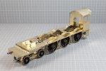
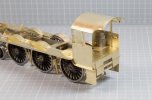
IMG_10767.jpg

IMG_10766.jpg
 

Scale7JB

Western Thunderer
Apparently I’m straightening out buckled damper doors on Pitchford on Saturday so let me know if you need undercarriage shots.

JB.
 

SimonT

Western Thunderer
JB,
Some shots of that area and other ashpan bits would be very useful. Also the area around the the back of the driver's side steps and the injector on that side, if they haven't moved it forward. By chance I am working on the replacement chassis for the Hall:D.
Thanks
Simon
 

simond

Western Thunderer
Mick,

at risk of granny and eggs here, if I have to solder two bits of sheet metal at an angle, without tabs etc, I cut a couple of intersecting razor-saw slots at the appropriate angle in a bit of end grain scrap wood, and use that to hold the brass for the soldering.

it saves the smell of singed octopus.

there’s a picture in my RMW thread about my Garratt, I’d post a link but their servers are struggling at the moment.

atb
Simon
 
Top