simond
Western Thunderer
As promised, a brief history of what happened since the Arduino thread began, in the hope that it will be a useful reference for anyone else doing this sort of thing;
The aim of the project was to provide a remote control panel for my 7mm Porth Dinllaen "might have been" loco shed model, with the following control functions;
Points - there are 7 points and a catch on the layout, and there would be one more to separate the shed road to the carriage sidings. Two of the points form a crossover, the catch is on the coal road ramp, and is operated by the same lever as the point it protects, thus 6 levers are currently required and I built in 8. The points are driven by Tortoises, with live frogs switched by the built-in switches in the motors.
Turntable - the turntable has 3 accessible roads, thus 6 logical positions
Lighting - I wanted to be able to operate the lights, preset the brightness and then switch on and off from the panel
DCC Program road - the front siding/headshunt is set up as a program track - there is a DPDT relay that disconnects the DCC operational supply and connects the track to the programming outputs. This relay is interlocked with the Tortoise so it can only be thrown if the points are set so that the siding and headshunt prevent a loco crossing onto the operational track.
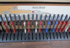
Control panel - the panel is an old RS box from some test equipment that was being thrown out at work - it was rescued from the bin, and used on the old Greater Windowledge Railway prior to PD loco. It's a good argument for recycling, I don't know how old it was when I got it but it must be at least 15 years older now. It came with a 25-way D-connector on the back panel, and a 2m 25-way lead.
On the GWR, there were some points and a couple of ground signals, and the whole ensemble could easily be controlled using individual cores in the 25 way lead. I also arranged for a couple of 4mm sockets on the back of the panel, to have track or programming supply to them, so I can put the rolling road on the workbench and simply plug it into the panel. I also connected 4 cores to a DIN 5-way socket so the DCC controller would plug in as well. That worked on the GWR, but won't, with the t/t and lights, and programming, and more points, on PD loco, so something had to be done.
What I did was, in hindsight, not ideal, but was a step on the way - I put an Arduino Mega inside the panel, and created a couple of modules to be mounted under the baseboard to control points and turntable. Each of these had an Arduino Nano as a slave processor, and I connected them together using the I2C protocol which is built-in to the Arduinos. Someone on RMW told me that it wouldn't work, and he was right-ish. It did work quite well, but it was far from reliable, and became more and more of a frustration, as it was necessary to reset the control panel Arduino almost every five minutes. I never got around to getting the programming track control or lighting to work as it was evident that changes were necessary.
I then found a convenient CAN (Controller Area Network) interface for the Arduino, and started playing with that, and getting very frustrated because it never quite worked. I think programming can be like that, there is a (usually) simple error or step that is needed, and despite searching and searching, it sometimes simply doesn't make itself obvious, until it does, and then you wonder why it took so long to do something so simple...
CAN is very flexible, robust and capable of being far faster than would be needed in most model applications - it is also able to run an extended network so I doubt there is any issue with even a large garden railway. CAN interfaces are dead cheap, I think I paid £11 for four, and clone Arduinos are a similar price, so you could imagine making a slave "node" to control, for example, a junction on the other side of a garden railway, with a couple of point motors and maybe four signals, and connecting that back to the control panel using the network.
A diagram of the network hopefully clarifies what's going on. Each of the four slaves has a CAN interface and a Nano, the control panel has an interface and a Mega, simply because it has more inputs and outputs.

I've added most of the sketches to this thread, there is one missing, it's on another laptop, so I'll copy it over and add it. I also have an Excel file with the stripboard layouts for each of the slaves if anyone would like a copy.
There's probably lots more I could say, but it's probably easier to answer questions if there are any.
As I said three years ago at the top of this thread, I have some programming experience but am not at all a pro - and I am not an electronics engineer either, nearly everything I've done is just adding commercially available modules to Arduinos, I guess I pushed that boundary a bit making the points controller board, but there is nothing here that anyone who can solder and follow a diagram can't make.
There is also MERG, who have their own C-Bus system. This involves more soldering of components, and more opportunities for Cap'n Cockup to visit... so I avoided it. It's very definitely an alternative approach with all the same advantages. I guess it's whatever floats your boat.
Any questions, please ask away, I'll try to give useful answers!
cheers
Simon
The aim of the project was to provide a remote control panel for my 7mm Porth Dinllaen "might have been" loco shed model, with the following control functions;
Points - there are 7 points and a catch on the layout, and there would be one more to separate the shed road to the carriage sidings. Two of the points form a crossover, the catch is on the coal road ramp, and is operated by the same lever as the point it protects, thus 6 levers are currently required and I built in 8. The points are driven by Tortoises, with live frogs switched by the built-in switches in the motors.
Turntable - the turntable has 3 accessible roads, thus 6 logical positions
Lighting - I wanted to be able to operate the lights, preset the brightness and then switch on and off from the panel
DCC Program road - the front siding/headshunt is set up as a program track - there is a DPDT relay that disconnects the DCC operational supply and connects the track to the programming outputs. This relay is interlocked with the Tortoise so it can only be thrown if the points are set so that the siding and headshunt prevent a loco crossing onto the operational track.
Control panel - the panel is an old RS box from some test equipment that was being thrown out at work - it was rescued from the bin, and used on the old Greater Windowledge Railway prior to PD loco. It's a good argument for recycling, I don't know how old it was when I got it but it must be at least 15 years older now. It came with a 25-way D-connector on the back panel, and a 2m 25-way lead.
On the GWR, there were some points and a couple of ground signals, and the whole ensemble could easily be controlled using individual cores in the 25 way lead. I also arranged for a couple of 4mm sockets on the back of the panel, to have track or programming supply to them, so I can put the rolling road on the workbench and simply plug it into the panel. I also connected 4 cores to a DIN 5-way socket so the DCC controller would plug in as well. That worked on the GWR, but won't, with the t/t and lights, and programming, and more points, on PD loco, so something had to be done.
What I did was, in hindsight, not ideal, but was a step on the way - I put an Arduino Mega inside the panel, and created a couple of modules to be mounted under the baseboard to control points and turntable. Each of these had an Arduino Nano as a slave processor, and I connected them together using the I2C protocol which is built-in to the Arduinos. Someone on RMW told me that it wouldn't work, and he was right-ish. It did work quite well, but it was far from reliable, and became more and more of a frustration, as it was necessary to reset the control panel Arduino almost every five minutes. I never got around to getting the programming track control or lighting to work as it was evident that changes were necessary.
I then found a convenient CAN (Controller Area Network) interface for the Arduino, and started playing with that, and getting very frustrated because it never quite worked. I think programming can be like that, there is a (usually) simple error or step that is needed, and despite searching and searching, it sometimes simply doesn't make itself obvious, until it does, and then you wonder why it took so long to do something so simple...
CAN is very flexible, robust and capable of being far faster than would be needed in most model applications - it is also able to run an extended network so I doubt there is any issue with even a large garden railway. CAN interfaces are dead cheap, I think I paid £11 for four, and clone Arduinos are a similar price, so you could imagine making a slave "node" to control, for example, a junction on the other side of a garden railway, with a couple of point motors and maybe four signals, and connecting that back to the control panel using the network.
A diagram of the network hopefully clarifies what's going on. Each of the four slaves has a CAN interface and a Nano, the control panel has an interface and a Mega, simply because it has more inputs and outputs.
I've added most of the sketches to this thread, there is one missing, it's on another laptop, so I'll copy it over and add it. I also have an Excel file with the stripboard layouts for each of the slaves if anyone would like a copy.
There's probably lots more I could say, but it's probably easier to answer questions if there are any.
As I said three years ago at the top of this thread, I have some programming experience but am not at all a pro - and I am not an electronics engineer either, nearly everything I've done is just adding commercially available modules to Arduinos, I guess I pushed that boundary a bit making the points controller board, but there is nothing here that anyone who can solder and follow a diagram can't make.
There is also MERG, who have their own C-Bus system. This involves more soldering of components, and more opportunities for Cap'n Cockup to visit... so I avoided it. It's very definitely an alternative approach with all the same advantages. I guess it's whatever floats your boat.
Any questions, please ask away, I'll try to give useful answers!
cheers
Simon
Attachments
Last edited:


")
") and if I am so enthusiastic, I might need to get my hands dirty ...
and if I am so enthusiastic, I might need to get my hands dirty ...