Scratchbuilt Sentinel - 9129

adrian

Flying Squad
As alluded to in my general workbench thread I have decided to return to a little scratch building as light relief from kit building, with 2 projects started. I'll probably flit from one to the other as I ponder on the next stage of the build. However the Sentinel is the first one to see any real progress - so this was the taster I left with members.
Sentinel_1 - 2.jpeg

These form the beginning of Sentinel Job number 9129 which will require a little background information.

From my previous postings it is fairly evident I have a penchant for Sentinels, my first effort was a scratch built Y10, I've actually built 2 of them and the LNER only ever had 2 in the class! In scratch building I wanted to build something that wasn't available in a kit and be something slightly different and quirky. A couple of years ago the Industrial Railway Society published a nice book on Sentinel Locomotives and Railcars which I added to my collection. Whilst flicking though it I happened across Sentinel 9129. This was referenced in previous Sentinel bibles "The Sentinel" by A&J Thomas as a purely drawing board proposal. However the IRS book fleshed out a few more details about the loco.

The loco 9129 was a design of "General Purpose" engine advertised by Sentinel for a custom built range using a Doble twin cylinder axle drive unit where the customer could specify gauge and number of axles etc. The IRS book states that LNER loco committee agreed to the purchase of 9129 in 1934, the engine was to be painted in Goods engine black and lined red with a running number of 24. Allegedly the work was subcontracted out to Bagnall Ltd of Stafford for the build and a number of components were built and "at least one engine was built and tested" before the contract was cancelled in 1936. That was enough for me - to make something different the following is a build of Sentinel 9129.

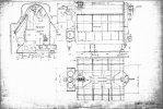
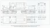
I have only the following engineering diagram to work from because as far as I know there are no photos of any loco built. However I will use some of the other builds for Peru and Columbia to have a guess at the final configuration.
Sentinel_1 - 1.jpeg
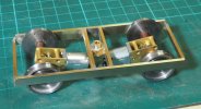
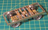
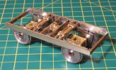
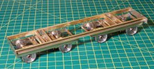
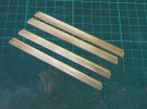
So work started on the power units, the posted images forming the sides of bogies - tacked together with some U channel.
Sentinel_1 - 4.jpeg

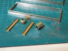
The central pivot was turned from some hex brass
Sentinel_1 - 5.jpeg

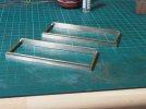
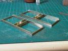
From the drawing the central bolster was formed from a couple of U channels and the hex brass provided a suitable spacing to match the drawing.
Sentinel_1 - 6.jpeg

The next stage is to work out the drive arrangement.
 

AJC

Western Thunderer
Hi Adrian,

That's extremely interesting - not least because it's a Sentinel I didn't know about. It's an entirely recognisable bit of Sentinel development, of course, with the patent Woolnough boiler and bogie underframe. The subcontract to Bagnall doesn't greatly surprise me - a lot of this went on: Sentinel had its own subcontract arrangement for the conversions from conventional locos it did; Bagnall contracted for Brush, much later, and Peckett built the frames for a few standard gauge Rustons - and it makes sense for the structures to be built offsite and for Sentinel to supply the mechanical bits. The axleboxes and so on look absolutely standard (in as much as Sentinel ever built anything exactly the same way twice).

Adam
 
Last edited:

adrian

Flying Squad
A small update. The Sentinel design for this offered either a simple or compound Doble engine - axle mounted.

Sentinel-2 - 4.jpeg

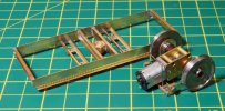
Inspired by some of @Giles efforts with micro-motors and gearboxes I thought I'd try and emulate this arrangement. I worked out there was just about room to squeeze a couple in.

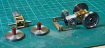
So I got a couple of motors from ebay and some wheels from Roxy. The wheels were skimmed and reprofiled for Scale7 and then how to mount them on the gearbox as the final drive axle was fairly well secured. The option I've gone for is an extended tufnol insulation bush to slip over the gearbox axle. I will then probably drill and fit a taper pin to lock them to the axle.

I have then been working out the suspension arrangement, opting for short pivoted arms holding little roller bearings. The pivot point trying to match the torque arm pivot point of the prototype when the dummy outside axleboxes are fitted.

Sentinel-2 - 1.jpeg

Fortunately just enough room on the wheelbase to get the motors in room to get to the bogie attachment point.

Sentinel-2 - 2.jpeg

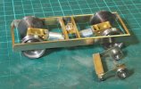
Now I just need to work out how to work to mount the pivot beam in the bogie and also the motor mounting needs to be flexible, if clamped to the bogie it won't allow the gearbox to float on the axle. Also to be seen on the torque arm is a tab on the top, this will be twisted by 90 degrees to provide a fulcrum point for fitting a length of spring wire for the suspension once I work out where the the other end will be fixed to the bogie!!

Sentinel-2 - 3.jpeg
 

adrian

Flying Squad
Just went searching for a photo as companion to Adrian's drawing but came up with nowt. A rare beast indeed.
It's a bit of a double edged sword and rather ironically having just mentioned it elsewhere could be classed as vapourware.

To the best of my knowledge there aren't any photos, unless there are some internal Bagnall ones floating around. Which makes it a rather interpretive build, on the other side it's going to be difficult for anyone to say I've got it wrong!

As mentioned my guide will be the Argentinian & Columbian locos - these were described as the prototypes for these "general purpose" locos.


Pencarrow

Western Thunderer
It's a bit of a double edged sword and rather ironically having just mentioned it elsewhere could be classed as vapourware.

To the best of my knowledge there aren't any photos, unless there are some internal Bagnall ones floating around. Which makes it a rather interpretive build, on the other side it's going to be difficult for anyone to say I've got it wrong!

As mentioned my guide will be the Argentinian & Columbian locos - these were described as the prototypes for these "general purpose" locos.


Streamlined monsters! Certainly going to be an eye to behold.
 

Super-Sentinel

New Member
Adrian,
Thanks for tackling this worthwhile project and I look forward to further updates. There will be no prototype photographs as none of the specifications for the frames/footplate, buffers & drawgear and cab bunker were ever issued. One engine was completed as a 6x6in two-cylinder simple plus a few ancillaries. The boiler may also have been built as there is a full set of drawings. Attached is a rather poor copy of drawing 17401 which may be of use to you as it gives the profile for the boiler casings. The locomotive was to be vacuum braked so you will also need to add LNER vacuum pipes at each end.17401 copy.jpg
 

Phil O

Western Thunderer
A 3 drum marine boiler, "there's lovely". My first tubing job as an apprentice was on one of those, but considerably bigger than that!!
 

adrian

Flying Squad
There will be no prototype photographs as none of the specifications for the frames/footplate, buffers & drawgear and cab bunker were ever issued. One engine was completed as a 6x6in two-cylinder simple plus a few ancillaries. The boiler may also have been built as there is a full set of drawings. Attached is a rather poor copy of drawing 17401 which may be of use to you as it gives the profile for the boiler casings. The locomotive was to be vacuum braked so you will also need to add LNER vacuum pipes at each end.
Thanks for the information - it all helps. I've been slightly distracted with my other "project" whilst pondering on the suspension arrangements but a little more progress has been made.
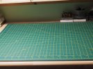
but first I was getting a little frustrated and fed up with a cluttered workbench so I treated myself to a new cutting mat and a good clear up.
Sentinel-3 - 1.jpeg

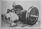
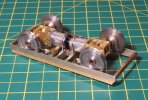
My initial trial for fitting the drive unit and suspension meant fitting additional cross braces and some small pads drilled and threaded 8BA to screw the drive unit to. I had to slightly dismantle them to drill a couple of holes in the central bolster to slide the wire spring. That sorted out the springing but the motors were still drag on the floor. On the full size loco there was a rubber mounted engine mount, the "lantern" style fitting can be seen in the prototype photo posted earlier. Although I wasn't sure whether to replicate it like this.

Sentinel-3 - 3.jpeg

Instead the first effort was a wire hoop from the main bolster - for one bogie it worked fine but the other bogie it didn't work out that well, it kept sticking. They were all built to the same method so I wasn't happy as it seemed a bit hit or miss.

Sentinel-3 - 5.jpeg

The bogie just didn't seem to sit very level and I couldn't work out why.

Sentinel-3 - 4.jpeg

So revised method was to move the restraint closer to the pivot point for the torque arms - I could also fit it to the drive axle so this is now a self contained unit - just 2 screws to fit it to the bogie frame.

Sentinel-3 - 6.jpeg

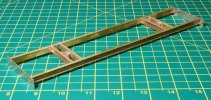
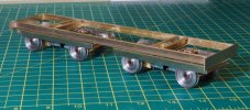
So attention then turned to making the frame to get a feel for the size of the loco. This is just some U channel cut to length and soldered together on a plate glass surface plate to keep it flat. The buffer beams are just tack soldered on at the moment.

Sentinel-3 - 2.jpeg

So setting it up it feels a little shorter than I was expecting it to be but it's a nice stage to get to. I always like to getting the basic chassis sorted first. Once I'm at this stage I can make a start on the upper body work and sort out where everything fits or carry on with detailing the bogies with axleboxes and brakes etc.
Sentinel-3 - 7.jpeg


Sentinel-3 - 8.jpeg
 

simond

Western Thunderer
Adrian,

this is a lovely bit of model engineering, combined with interesting history.

please could you tell me which ratio of mini-motors you got, and what speed they produce. I had the same idea to produce motor bogies for an ex-Big Big Hymek, but unfortunately it’s not going to cut the mustard, as it’ll be flat out at 17mph.

I don’t think I got it wrong, I suspect the seller sent a different ratio to that which I ordered, but would be interested to have a comparison point.

thx
Simon
 

adrian

Flying Squad
please could you tell me which ratio of mini-motors you got, and what speed they produce. I had the same idea to produce motor bogies for an ex-Big Big Hymek, but unfortunately it’s not going to cut the mustard, as it’ll be flat out at 17mph.
I got a couple, these are the allegedly 136rpm units but not tested yet so yes it will be about a scale 17mph. Which maybe fine for a shunting loco. I also got a set of 381rpm units, which would be around 40-45mph scale speed. It's one of the reasons I've built it this way with the self contained axle units so hopefully it will be easy to swop motors without too much hassle if it's too slow or too quick.
 
Top