You are using an out of date browser. It may not display this or other websites correctly.
You should upgrade or use an alternative browser.
You should upgrade or use an alternative browser.
Pivoting point blades in Shropshire
- Thread starter NickC
- Start date
Dog Star
Western Thunderer
When building turnouts with loose heel switches - well the switch does rotate about the end of the closure rail - I use the brass fishplate castings from the S7 Stores and probably Phoenix Precision Paints (the PW arm). I solder the fishplate to the closure rail and pin the switch rail through a hole drilled to represent a fishbolt/nut.
Stevesopwith
Western Thunderer
I've used the brass 'H' type fishplates from C & L.
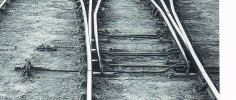
I file a recess in the web of the closure rail and switch blade to accommodate the fishplate joining crosspiece.
I taper the inside faces of one end of the plate to reduce the pressure needed to pivot ( not spring ) the switch. This also gives the correct 'kink' of the switch relative to the closure rail, as evidenced in the attached image.
I solder the untapered end to the switch, provide a flexible wire feed to the switch, and cut insulating gaps in the crossing area.
The switch blades are held in position by the under-baseboard TOU, and the stretcher bars are cosmetic.
Attachments
Dog Star
Western Thunderer
I make a 7mm loose heel switch using separate closure and switch rails because:-
1/ a continuous closure / switch rail does not give the visual impression of the prototype;, just as illustrated by Steve Sopwith;
2/ 7mm rail is stiff enough that turnout motors can have difficulty in "throwing" the switch.
Steve @Stevesopwith , how do you stop the switch rail from moving towards the toe of the turnout?
SimonT
Western Thunderer
I've had a string of successful layouts with loose heel switches which used the brass fishplate method, soldered to the switch rail and crimped to the closure rail. Swithc rails walking down the turnout is prevented by a rugged sub-baseboard tiebar/switch jobby. They used to be a length of solid 1/4"ish square rod with brass tubes let into the rod to hold droppers from the switch rail. The rod slid in square tube holders bonded to 2mm thick sheet to screw to the baseboard. Now I use my own 3D printed device to do both jobs.
ICH60
Western Thunderer
Have you any pictures of said turnouts?I've had a string of successful layouts with loose heel switches which used the brass fishplate method, soldered to the switch rail and crimped to the closure rail. Swithc rails walking down the turnout is prevented by a rugged sub-baseboard tiebar/switch jobby. They used to be a length of solid 1/4"ish square rod with brass tubes let into the rod to hold droppers from the switch rail. The rod slid in square tube holders bonded to 2mm thick sheet to screw to the baseboard. Now I use my own 3D printed device to do both jobs.
simond
Western Thunderer
V
Nick,
I’m not sure exactly what you mean by this.
If you mean that you want to electrically isolate the switchblade from the adjacent stock rail, I can only ask why? If your stock rail and switch blade are electrically connected, you avoid any risk of the wheel shorting these, but of course you will need to isolate the closure rails from one another, and the frog / common crossing.
regarding loose heel pivots, I have used brass (and loose Peco) fishplates, I have also used a strip of phos bronze soldered to both closure and switch rails.
They are supposed to be insulated from the adjoining rail.
Nick
Nick,
I’m not sure exactly what you mean by this.
If you mean that you want to electrically isolate the switchblade from the adjacent stock rail, I can only ask why? If your stock rail and switch blade are electrically connected, you avoid any risk of the wheel shorting these, but of course you will need to isolate the closure rails from one another, and the frog / common crossing.
regarding loose heel pivots, I have used brass (and loose Peco) fishplates, I have also used a strip of phos bronze soldered to both closure and switch rails.
Sorry if I was not clearer! I want to pivot the point blades as near the end as possible but they have to be electrically isolated from the closure rails as they are a unit with the crossing. Therefore, I cannot use a metal fishplate and don't fancy a plastic one; I doubt it would last long.
Thanks for all the ideas so far.
Thanks for all the ideas so far.
ChrisBr
Western Thunderer
All it needs it a sliver of plasticard (preferably black not white) glued to the end of each closure rail before you get to the crossing and filed to the rail profile, becomes almost invisible......Ought you to start thinking about isolating the closures from the common crossing?
[you know it makes (a) sense and (b) the loose heel pivot a more enduring solution.]
simond
Western Thunderer
Or cut the rail and fill the cut with Araldite, or use a plastic C&L fishplate at the (prototypical) joint to the common crossing.
my experience is that connecting switch blades and stock rails electrically is by far the better way to go, and I do it as a matter of course. YMMV.
my experience is that connecting switch blades and stock rails electrically is by far the better way to go, and I do it as a matter of course. YMMV.
SimonT
Western Thunderer
I tried that with a steel wire "dropper" silver soldered to the bottom of the switch rail and a tube bearing set into the timber. It didn't hold the swich rail to gauge due to the play/slop required to let the switch rail pivot.I want to pivot the point blades as near the end as possible
Have you any pictures of said turnouts?

The gap at the joint of the curved switch is caused by the C & L fishplates being narrower than the web of the rail. There was a thread on the subject a good few years ago as the C & L bits no longer matched rail. I later took this switch off and attacked the web with a file to make it match the fishplate better.
Simon
Pencarrow
Western Thunderer
I've had a string of successful layouts with loose heel switches which used the brass fishplate method, soldered to the switch rail and crimped to the closure rail. Swithc rails walking down the turnout is prevented by a rugged sub-baseboard tiebar/switch jobby. They used to be a length of solid 1/4"ish square rod with brass tubes let into the rod to hold droppers from the switch rail. The rod slid in square tube holders bonded to 2mm thick sheet to screw to the baseboard. Now I use my own 3D printed device to do both jobs.
Good morning, do you have any photos to show the 3D printed devices?
SimonT
Western Thunderer
Chris,
found this 9 year old pdf which I couldn't convert into a graphics file, so this is a screen snip of the set up.

We used these for all the turnouts on Aberbeeg with no troubles at all and they are on the new layout. The slider sits in two slots between the sleepers and is kept attached to the baseboard by the small housing. The Tiebars were a look at 3D printing. I had some of them on Aberbeeg. The Tortoise could go at either end and sat in an adjuster tray. I produced some sliders with extended ends to suit different siting requirements. Not shown are the wire droppers.
If you would still like to see the set up on a layout, I'll go out to the shed and take some photos, especially as I've finished chewing the porridge!
Simon
found this 9 year old pdf which I couldn't convert into a graphics file, so this is a screen snip of the set up.
We used these for all the turnouts on Aberbeeg with no troubles at all and they are on the new layout. The slider sits in two slots between the sleepers and is kept attached to the baseboard by the small housing. The Tiebars were a look at 3D printing. I had some of them on Aberbeeg. The Tortoise could go at either end and sat in an adjuster tray. I produced some sliders with extended ends to suit different siting requirements. Not shown are the wire droppers.
If you would still like to see the set up on a layout, I'll go out to the shed and take some photos, especially as I've finished chewing the porridge!
Simon
Pencarrow
Western Thunderer
Chris,
found this 9 year old pdf which I couldn't convert into a graphics file, so this is a screen snip of the set up.
View attachment 180745
We used these for all the turnouts on Aberbeeg with no troubles at all and they are on the new layout. The slider sits in two slots between the sleepers and is kept attached to the baseboard by the small housing. The Tiebars were a look at 3D printing. I had some of them on Aberbeeg. The Tortoise could go at either end and sat in an adjuster tray. I produced some sliders with extended ends to suit different siting requirements. Not shown are the wire droppers.
If you would still like to see the set up on a layout, I'll go out to the shed and take some photos, especially as I've finished chewing the porridge!
Simon
That's very interesting Simon. I'm using the Tortoise mounting plates under the layout which are equivalent to your under-board print. Those cosmetic tie bars look like a great solution. Yes, photo appreciated if possible.

Les Golledge
Active Member
Hi All,Hi All,
Have a look at this thread of a layouts construction on Templot as it shows how the author pivots the switcblades on his layout, to me this is a excellent method:- EM gauge slip
Regards,
Les.
Just found another link to the same thread:- http://85a.co.uk/forum/view_topic.php?id=2547&forum_id=6
Regards,
Les.