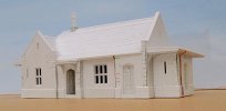
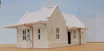
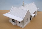
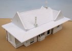
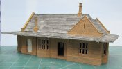
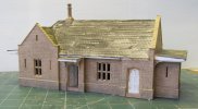
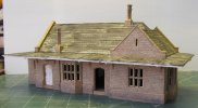
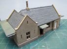
Acorn Wood Station

Stuart Birks

Active Member
Having completed the village it was time to start the actual station. I could use all that I had learnt making the village buildings to help with the construction.
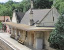
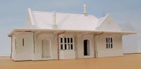
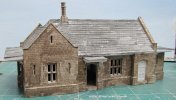
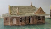
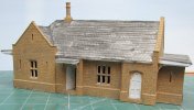
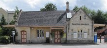
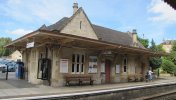
As a building to copy I picked Bradford-on-Avon. It is the right size and has an interesting level of detail. The only minor problem is the lovely bay window on the end of the building is at the wrong end for my location and so I have simply created a mirror image of it.
IMG_5374.JPG

IMG_5423.JPG

IMG_5427.JPG

I took a lot more photos than this to give me a lot of the details.

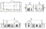
The first step was to make a 2D CAD drawing which I could then use to determine all the dimensions and details. This is just a screen grab of a very detailed drawing with each wall element being detailed.
station full.jpg
Now I was in a position to start construction

Stuart
 

Stuart Birks
Active Member
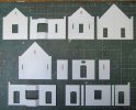
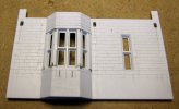
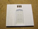
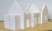
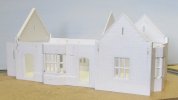
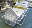
An aparently simple building like this needs 14 wall sections which are detailed before joining them together. All the joints are mitred so the stone courses flow properly around the corners.

IMG_7126.JPG

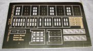
I had an etch made for the window frames, doors and the canopy brackets.

IMG_7484.JPG

A combination of the etched parts with profiled plastic sections gives a good structure to the windows and doors.

IMG_7505.JPG

IMG_7511.JPG

IMG_7513.JPG

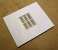
All the wall panels have 5mm added to the bottom so that the building sits into the platform rather than on top of it. This prevents any gaps showing underneath it. The stone courses are scribed into the plastic walls. The bits of green are filler, some to fill gaps and some where I changed my mind about a stone joint and so I moved it.
Stuart
 

LarryG

Western Thunderer
I like this approach very much. It is very satisfying measuring up a structure and planning how it is to be constructed. I see from the etch this project has been on the go for some time.
 

Stuart Birks
Active Member
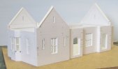
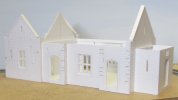
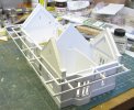
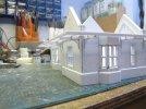
Once all the wall panels are complete they can bee assembled into the building. Great care was taken to make the lengths very accurate so that any accumulated error was negligable so it came out the right size and square when it was all joined.

IMG_7520.JPG

IMG_7521.JPG

IMG_7522.JPG

IMG_7523.JPG

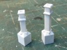
The next thing I made were the chimneys. Although small they have a very complex shape which took quite a lot to assemble. They will go through holes in the roof rather than trying to cut the bottom at the correct angle.

IMG_7587.JPG

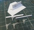
It was now time to work on the canopy. I included the brackets on the etch I had made and these had little bits sticking out for location. I made a simple jig to ensure that they were glued correctly in the beams.

IMG_7596.JPG

Holes had been pre-drilled in the walls and so it was a simple job to get them in the right place. The beams were made over length on the inside of the building so they could be re-inforced with a gusset plate.

IMG_7598.JPG

IMG_7599.JPG

IMG_7601.JPG

Just need the covering on now.
Stuart
 

Stuart Birks

Active Member
Now the roof and canopy are added. The slates are made from strips of plasticard scribed and set on very thin small strips to create the step. Drain pipes were made from coper wire with thin wire wrapped around and soldered to create the pipe joins. The gutters are just half round plastic strip with one edge slightly filed to create a flat for gluing it. A while age I made a gutter with the internal groove in it but it didn't show even close up so now I dont bother.

IMG_8254.JPG

IMG_8255.JPG

IMG_8256.JPG

IMG_8257.JPG

IMG_8258.JPG

Now its on to the painting.
Stuart
 

ovener

Active Member
Your model is coming along very nicely. I like the idea of the copper wire for drainpipe - I may have to steal that idea try that myself. I've never been totally happy with plastic downpipe (full size or modelling!)
 

jonte

Western Thunderer
Marvellous attention to detail, Stuart.

May I ask: what tool did you use to scribe the stonework?;
how did you achieve the ‘scribed(?)’ moulding around the edges of door and window reveals?

Many thanks.

Jon
 

jamest

Active Member
Hi,

Great work on the building and really interesting to see your approach and the steps involved.

I too would like to know what tool you use to scribe the stonework. I never seem to have as much success. Investors used a pointed tool and a ’vee’ but I’ve never got the same results as you.

regards
James
 

Stuart Birks

Active Member
Thanks for the comments.
The scribing was done with a simple hook ground from a knife blade. the cutting edge was removed and the thickness ground down to a thickness of 0.2mm not to a point. This gives a realistric mortar width.

IMG_1135.JPG

The straight lines were done with a ruler, the curves around the doorways were done freehand following a pencil line.
The scribing does raise a burr on each side which has to be removed. I did it by scraping it with a knife blade.
The depth on the window and door frames was done by simple gluing a second layer behind the window opening with a slightly smaller hole in it.
 

Stuart Birks

Active Member
The painting starts with a dark wash made thin enough that ir runs into the mortar grooves easilly. It looks a real mess at the first stage but that is fine. It forma a bit of pre-shading for the later layers.

IMG_8259.JPG

IMG_8262.JPG

Everything from this point on is layers built up by dry brushing with the layers gradually getting thinner and lighter. It still looks a boring mess after the first layer but it gets better.

IMG_8278.JPG

IMG_8279.JPG

Stuart
 

jonte

Western Thunderer
Thanks for the comments.
The scribing was done with a simple hook ground from a knife blade. the cutting edge was removed and the thickness ground down to a thickness of 0.2mm not to a point. This gives a realistric mortar width.

View attachment 193318

The straight lines were done with a ruler, the curves around the doorways were done freehand following a pencil line.
The scribing does raise a burr on each side which has to be removed. I did it by scraping it with a knife blade.
The depth on the window and door frames was done by simple gluing a second layer behind the window opening with a slightly smaller hole in it.
Many thanks for sharing, Stuart.

I think I’m right in saying it’s similar to the ‘Olfa’(?) cutter which I’ve often thought of investing in, so think I’ll add one to the collection.

Jon
 

D6356

Western Thunderer
Lovely work and having visited the original station, even as a mirror image a lovely rendition and super quality modelling.
Thanks for sharing
Robert
 

Stuart Birks

Active Member
The knife is similar to the Olfa cutter but as far as I can tell the Olfa produces a V groove wheras I have ground mine to produce a square bottomed groove exactly the width I wanted. It would be simple to grind a different blade for a different width groove. In reality I doubt if you could tell the difference.

As I said the paint job continues with building up layers to get the colour right with some variation for weathering. It is also slightly dirtier near the ground.

IMG_8284.JPG

IMG_8285.JPG

The roof follows the same process but in grey.

IMG_8313.JPG

IMG_8318.JPG

The canopy is not the right colour here.

Both slate and cotswold stone have a huge variety of shades so virtually anything goes as long as it looks ok.
Stuart
 

Stuart Birks

Active Member
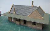
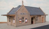
This is the finished building. I made a small board to see what it would look like as the layout and platform ere not built at this stage.
This is the non-platform side and once mounted on the layout this side will not really be able to be seen.

IMG_8457.JPG

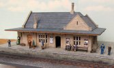
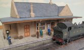
The platform side with some figures added.

IMG_8458.JPG

The end bay window which was one of the features that made me pick this building in the first place.

IMG_8459.JPG

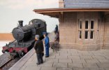
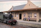
A couple mores shots with a loco in them.

IMG_8461.JPG

IMG_8464.JPG

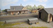
This is it finally in position on the layout. I am very happy with the result.

IMG_0106.JPG

Stuart
 
Top