Lancastrian
Western Thunderer
Just to resurrect this thread, I'm looking at S7 for a few locos I'm currently working on in QCAD, so what advice from the genius-pool on minimum clearance measured from frame face to rear of wheel ? For example, is 1mm just about enough, or more than enough ?

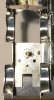
The red line is 1.2375 mm.
Blue lines are the frames as currently designed.
Pink lines are frames at prototypical width.
Green line indicates rear face of wheel.
Ian
Ian
The red line is 1.2375 mm.
Blue lines are the frames as currently designed.
Pink lines are frames at prototypical width.
Green line indicates rear face of wheel.
Ian
Ian
") .
.