7mm MOK BR Standard 4MT Tank

P A D

Western Thunderer
Well now that the Finney A3 is done for now, it's time to move onto the next build. I know there have been a few builds of this kit on various forums since its introduction, but here's my two penn'orth.

First a looks at what's in the box. Here are the myriad of castings and the Slaters wheels.
20180514_180817.jpg

And the etchings.
20180514_180818.jpg


20180514_181525.jpg

And very extensive and profusely illustrated instructions. There are a whole host of prototype photos of 80002 in the running shed at Howarth, but I've also been up to Oxenhope where it is now stored out of use and taken pot loads more. I even got permission to climb up onto the running plate and take some shots of the tank tops and also in the cab.
20180514_181748.jpg

Cast part identification.
20180514_181657.jpg

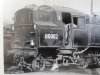
And finished already!
20180514_205319.jpg

20180514_205825.jpg

Only joking of course. This is the DJB one I built for my brother some years ago, so it will be good to compare and contrast the two. It's a pity the running plate above the cylinders is too low, but I knew that at the time and decided to leave it. I wish I'd set it in forward gear though.

Cheers,
Peter
 

dibateg

Western Thunderer
Peter - I found this kit a most enjoyable build, I'm sure you will make a super job of it as usual!

Regards
Tony
 

P A D

Western Thunderer
Many thanks Tony.
Did you write your build up on here or RMW? I searched and can't find it.

Anyway, a modest start has been made. I'm quite impressed with the level of cusp on the etchings, or should I say lack of it. What there is, is very fine and doesn't need filing for the parts to fit. It doesn't say in the instructions so I rang Dave Sharp to check. A very helpful chap. I will however clean up any cosmetic edges and of course where there are fret tabs. That said, most of them are on the end of the mini tabs that locate the parts before soldering, and as they are sacrificial, there's no need to remove the fret tabs.

Here are the frames with the horn guides and compensation beams fitted . The lower one shows the outside of the frame after the twisted tabs to locate the horn guides were snipped and cleaned up. Snipping them as close as possible to the frames meant that a simple rub on 600 emery paper was enough to smooth them off and no file marks. Not that this matters on the frames, as there is a cosmetic overlay to be fitted late.
20180515_201447.jpg

Here's another shot showing the frames with some of the spacers folded ready for fitting. It's a time saver not having to file the edges of these. 20180515_163203.jpg

I test fitted the sliding axle bearing and they all fitted perfectly and ran smootly in the guides.

Next the ash pan. This at first looks quite complex and rather like one of those 3D gig saw puzzles, but is actually quite straight forward. Here it is held together with only the twisted mini tabs. 10 pieces in perfect alignment and not a drop of solder applied yet. A brilliant piece of design.
20180515_183604.jpg
20180515_183458.jpg

It was possible to get the iron in and solder completely from the inside, so other than a rinse under the tap, no cleaning up was needed. That said, I did scrape away the excess to tidy it up, but that is just my preference. Here it is after snipping the tabs and rubbing down on 600 paper.20180515_183303.jpg
20180515_183224.jpg
20180515_183339.jpg

So this is what we have so far.
20180515_183059.jpg

Cheers,
Peter
 

Genghis

Western Thunderer
I have one of these in the cupboard, so will follow this thread with more than the usual keen interest!
 

Dikitriki

Flying Squad
Hi Peter,

There are the threads mentioned above by Dave, but please don't let those put you off from doing a fully detailed build thread yourself. Everyone has a different take and as I have one to do too, I would appreciate and enjoy an exposé similar to that of your A3.

Richard
 

P A D

Western Thunderer
Many thanks Dave.
I found both builds after I posted but the research link is very useful.

Richard,
No worries on the other builds putting me off doing an expose as you put it. I shall do it as per the A3 thread.

Personally I like to read as many builds as possible on a kit, as it always useful see how many ways the cat can be skinned.

Cheers,
Peter
 

Dog Star

Western Thunderer
Plus this topic....

BR 4MT research material

where, with the help of Jeanpaul, the question of spring suspension is put to bed - the kit represents a modification made to one at least) 4MT post privatisation, the photos on page 3 of the above topic illustrate original fitment.

Adrian has highlighted on his research topic (see Daifly's post above) that there are two styles of return crank and the kit supplies just one version. The "other" version is included in the MOK 76000 kit and a request to Dave Sharp brought forth the correct part for 80136 (plus castings for the speedometer and crank).

Advice received when Peter started his model was to add the spring suspension brackets to the frame plates before assembly of the frame as the ashpan interferes with access to the brackets (for soldering).

regards, Graham
 

P A D

Western Thunderer
So despite the heads up from Graham, I've assembled the frames and overlooked to add the spring suspension brackets beforehand. :headbang:

We'll see how that pans out later, but here's the right hand frame with the frame stretchers added. No solder yet just the mini tabs twisted.

20180518_172813.jpg

And after adding the left hand frame. You need to start at the rear end and feed the frame tabs into the slots in the buffer beam from an angle. This is mentioned in the instructions.
20180518_172737.jpg

It's then a matter of feeding the tabs through the slots working forward. All was well until I reached the stretcher with the tab circled on the frame. Try as I might I just could not get this tab in, so in the end I snipped it off. It was plain sailing after that.20180518_172656.jpg

Once all the tabs are located they can be twisted to lock it all together. The tabs marked with the black dots must not be snipped off at this stage as they are required for locating the frame and rear buffer beam overlays . I think it would help when locating the tabs, not to cut off the half etched fret tab, as these being thinner, should help to lead the tabs into the slots.

20180518_172603.jpg

Ready for soldering. I checked it was all square on a glass plate before going ahead.
20180518_172501.jpg

And a view of the underside after soldering.
20180518_185918.jpg

The right hand side after snipping off the tabs and fettling up. You don't need to worry too much about witness marks as they whole side is covered later with an overlay. The main thing is to ensure none of the tab stubs is proud.
20180518_190212.jpg

The left hand side has still to be snipped and fettled.
20180518_190818.jpg

So far so good. We'll see what issues if any, overlooking Graham's heads up creates later.

Cheers,
Peter
 

P A D

Western Thunderer
That's a lump of a chassis eh?!
JB.

Not as lumpy as an old Wills cast white metal one! Gone are the days, thank God.

One thing that occurred to me Peter - check that all the vent holes are etched in the cab, I recall I had to drill them out above the bunker. It will be easier to do that whilst its all still in the flat!
View attachment 87956

Thanks Tony.
Looking at this cropped image from the first post, it's clear the cab front plate has them, but not the rear. They are on the locker front plate so I can use that as a template. I have pencilled a note in the instructions so I don't miss it and then have to retro drill them afterwards. I note that you have added an angle "iron" between the tank vents. Is that a cover for a slacking pipe? As I recall you mentioned something in your thread.
20180519_100828.jpg

From the pictures of the DJB one I can see the holes in the cab front but not the rear. I'll ask me brother to check it. When this is done l may make some additions to his in areas that are lacking.

Have you ever built any DJB kits and what's your opinion of them? When they were around they were outside my budget, but looking at them on the stand at exhibitions they looked like good kits Certainly for their time and compared to the stuff I could then afford. The 4MT was bought with a long service award, but when I decided to part with it to fund more kits, my brother did a deal and kept it in the family.

Any further heads ups on the 4MT are most welcome and will be duly noted in the instructions. As you know the instruction book is a work of art, the best I've ever seen. I was impressed with the Martin Finney instructions but MOK have gone to a higher level. I haven't really studied the Finney 7 ones for the A4 in detail but they look to be of a similar high standard. (For the tender that is. The loco instructions are to follow)
Cheers,
Peter
 

P A D

Western Thunderer
My brother has just informed me the vent holes on the DJB one are present. I was going to say one up to DJB but as mentioned earlier the running plate above the cylinders is too low, so I'll call it 1:1 for now. :)
 

P A D

Western Thunderer
There are 15 holes in the rear cab plate of the DJB one. I cant remember if they were etched or if I had to drill them. Just been looking in Vol 3 of the RCTS book on BR Standard locos and I found a 7mm drawing tucked away in the back. No ide of its source but I believe ig was a 4mm drawing from one of the magazines that I enlarged on one of the fancy photo copies they had at work. It shows 16 holes.
20180519_143121.jpg

Looking at this photo of 80002 from the RCTS book would suggest 15 or 16 holes would be correct. You can also see what I believe is the slacking pipe and cover that Tony added.
20180519_130505.jpg

More research is needed.
Cheers,
Peter
 

Attachments

  • 20180519_130505.jpg
    20180519_130505.jpg
    387.6 KB · Views: 12
Top