Macton Waggon Diorama

michael mott

Western Thunderer
Today I was able to get some work done on the wagon, I was able to finish off the soldering of the buffer "castings" and registered them properly to the space on the inside so now that that is done I will make some new metal pieces to replace the wrong copper ones.

IMG_1122x1024.jpg

IMG_1124x1024.jpg
I think I will turn up the buffers first though. It felt good to get back to the wagon. I am wondering if I should put the wagon into its own thread rather than the layout one?

Michael
 

michael mott

Western Thunderer
Well this was a bear to turn I thought I would turn it up in two parts to save on machining away a ton of steel from .914 down to .210 So I thought about making the joint inside the "casting" so it wouldn't be seen.
IMG_1125x1024.jpg

Now I am thinking that I will turn the inside face and bore it to receive the shaft Cut off the blank from the parent piece on the Bandsaw and silver solder them together then turn the face. it will use much less steel and if the joint is done properly it won't be seen.

IMG_1126x1024.jpg
and a comparison with the tiny O gauge tramway loco.

IMG_1127x1024.jpg

Michael
 

michael mott

Western Thunderer
A bit more progress this afternoon. After rough shaping the back face of the buffer then cut off on the saw.

IMG_1129x1024.jpg

The head slipped onto the first buffer shaft I will do the silver soldering after all the shafts are made.

I wanted to see how things fit together so a dry assembly to check fits.

IMG_1133x1024.jpg
IMG_1140x1024.jpg
and overhead

IMG_1144x1024.jpg
I had no idea these simple wagons were so complex!

Michael
 

Mike W

Western Thunderer
Really lovely work Michael. Forgive me if you have already said, but what is the wagon? Looks like RCH 1923 and without an end door, but other than that I can't tell?

Mike
 

michael mott

Western Thunderer
These buffers seem to have been much more work than I anticipated. When I decided to make them in two parts I fabricated the parts so that there was a shoulder on the spindle part with a 1/8th inch diameter stub that would be silver soldered into the buffer platen (the big round thing at the end)
I do not enjoy silver soldering at the best of times and it needed a fair bit of heat.

Capture1150.JPG

when I was shaping the head it sheared off

The second one which I soft soldered did the same thing. Time for a rethink. I decided to bore through the head and make four new shafts and just use soft solder but now the integrity of the joint was larger bearing surfaces. I was able to use 7/32 drill to bore out the heads and still leave some filet material for the back side of the heads.

Capture1151.JPG

This method worked much better The colour of the solder is barely visible and the steel centre and the head blend in well once shaped.

Here the f0ur buffers have been shaped and slid into the frame

IMG_1154x1024.jpg
IMG_1159x1024.jpg
Next to make the small slot an the end of the shaft for the keeper pin to retain the springs.

Michael
 

michael mott

Western Thunderer
A long overdue update. :I am abandoning the Large scale buildings on these three 4 foot by 2 foot baseboards, the last bit of track being removed.

IMG_2453x1024.jpg

everything has now been stripped off, while I contemplate a change of direction. The bulk of the waggon build will continue after I have had the Carpal Tunnel Surgery, I'm told that it will happen some time within the next six months......sigh! I will create a small diorama for the waggon build. and can probably putz along with a few small bits I can make on the lathe with good breaks in between. A few tasks are ok and don't aggravate my right hand . The computer work is tough though.
I am going to see if I can rename this thread the waggon build diorama instead of locomotive works, because that will better reflect the ongoing nature of it. Once I have sorted out what to do with the 12 foot x 2 foot space on the baseboard I will start a new log for it.


Michael
 

michael mott

Western Thunderer
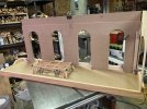
A bit of time has passed since the last entry, and while doing a bit of tidying up I thought that this small baseboard 53 x 12 inches would work for the wagon diorama so I did a little playing this afternoon with the elements from the old Crewe layout thinking about the orientation of a could have been section of the works.
IMG_0681x1024.jpg

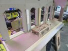
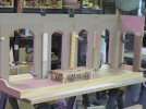
I am thinking that the view is looking out toward one of the doors with this section having the inside walls brick that has been whitewashed in the past and weathered with the general dirt and dust that accumulates in these places. the large opening would be the inside of the doors with standard gauge track leading outwith some 18 inch gauge down the centre. One of the arches would also have a doorway with a door and some 18 inch gauge track to a wagon turntable so that one of the Ramsbottom engines could theoretically head off to another section of the works. This much smaller section of the works seems much more doable and would allow for the overhead Crane to be parked against the wall coming out from the wall between the two middle openings. with the turntable lining up in front of the left hand arch opening, which could be a bit wider than the window arches.

IMG_0680.JPG
Please feel free to tell me this is an insane Idea and that I am nuts, but I do want to be able to take pictures of the wagon slowly coming together is a workshop type setting.
Perhaps the heat is getting to me! 29C today and forecast 32C tomorrow.
Michael
 

jonte

Western Thunderer
You’d have to be insane not to ‘like’ any of your mastery, Michael ;)

A big thumbs up here :thumbs::thumbs:

jonte
 

Osgood

Western Thunderer
This is an insane idea and you are nuts :thumbs:
But please keep reporting in!

Was there light at the end of the Carpal Tunnel?
 
Last edited:

John57sharp

Western Thunderer
I’ve just enjoyed reading this thread from the start over my first coffees. Michael your work is wonderful and inspiring, I hope you manage to finish this diorama and thanks for sharing all these insights.
cheers
John
 

Rob Pulham

Western Thunderer
I seem to have missed much of the wagon building part of this thread so I have had a very enjoyable catch up on it over breakfast this morning.
Looking forward to future progress Michael.
 

michael mott

Western Thunderer
This is an insane idea and you are nuts :thumbs:
But please keep reporting in!

Was there light at the end of the Carpal Tunnel?
Hi Tony thanks for commiserating, and yes the light at the end of the Carpal tunnel was bright enough that it has healed all the pain that I had in my right hand.

We'll probably start commenting on the bond of the brickwork. :)

Jim.
Oh No I shall have to do more research now and not just load the bricks with enough whitewash and grime to hide the bonds.

I’ve just enjoyed reading this thread from the start over my first coffees. Michael your work is wonderful and inspiring, I hope you manage to finish this diorama and thanks for sharing all these insights.
cheers
John
John thanks for your kind words, I think that this is small enough that I shall have more fun with it than the original which had just a bit too much repetition. One of the elements of this smaller diorama that i am really looking forward to getting into is the overhead crane, because there is enough room to have it fully operational.

I seem to have missed much of the wagon building part of this thread so I have had a very enjoyable catch up on it over breakfast this morning.
Looking forward to future progress Michael.
Rob thanks for thinking about this during your morning feast. One of the aspects of this little diorama is the photographic opportunities for taking pictures of wagons and possibly a small coach being assembled, of course it would have to be short like a horse box or possibly even a guards van down the road.

Michael
 

michael mott

Western Thunderer
A little more playing with the massing of the walls. I think the the doorway on the end was a bit too tight so have eliminated it and will have the one doorway at the open end on the back wall. The wagon turntable will sit in front of the door.
IMG_4805x1024.jpg
IMG_4807x1024.jpg
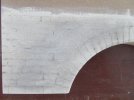
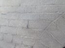
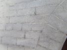
Also did a quick and dirty test of carving the bricks directly into the MDF using my small dremel like rotary tool basically the same tool that the folk use in the nail and pedicure business. takes 3/32 shaft size, for this test I used a tiny ball cutter a bit smaller than 1/16th diameter. Then slapped some Vanilla colour craft paint from the large craft store beginning with M. sprinkled it right away with some grey weathering powder using a stiff fan brush.
IMG_4800x1024.jpg

IMG_4803x1024.jpg

IMG_4802x1024.jpg

Definite possibilities, and much faster and much easier on the hands than embossing into the expanded foam board. I rather like the little bit of roughness to the bricks by doing it this way, gives it an aged look that I want slightly uneven mortar and non perfect bricks. (I told myself I was building a wall not a piano) I will get better with practice though.

Michael
 

michael mott

Western Thunderer
I have been looking for details of the Crewe works overhead cranes and the best photographs that i have seen are the ones in the foundry in the history of the Crewe tramway by Talbot. I am hoping somebody has a better lead to information about those early overhead cranes that were operated with chains. Details of the way they were constructed.

Michael
 

Osgood

Western Thunderer
Have you found the view of one of those iron foundry 5T cranes in FW Webb 1836 - 1906 A Bibliography by John Spink, pub. LNWR Soc.?
Perhaps a slightly better view of the moving carriage but curiously there appears to be no travelling hand chain on either side - photo taken at the foundry's opening May 1882.

I remember well the cast crane runway girders with their circular pattern!
 

michael mott

Western Thunderer
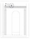
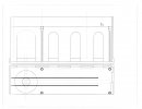
This is my drawing of the new diorama
a cross section showing the beams for the crane best i could come up with from the photograph in the Talbot book, If the pattern on the beam is actually circles I would like to have that confirmed somehow.
Scan 2 from autocad.jpg
And this is the overall plan I am putting the span of the crane at 40 feet for this diorama. the tramway track is 32mm and the standard gauge 100mm in round numbers

I spent an hour last evening carving in the bricks on the first section of wall on the right hand side.

scan from autocad.jpg

Michael
 
Top