Gladiator 7mm GCR 11F 4-4-0

LarryG

Western Thunderer
After Peter Chatham sent me a load of his paper I made 'Methfix' lining for awkward placed such as the backs of GCR Tenders between lamp brackets. Later on I made them waterslide after obtaining ultra-thin material from North America. Glad I'm well out of the game today though ha ha.
 

P A D

Western Thunderer
Hi Larry,
No idea how the lining will be done, but seeing as how it will be in GCR livery, I'm trying to make it as painter friendly as possible and unlike the Finney 7 T3, this kit lends itself to having the boiler removable. It will be finished as 502 Zeebrugge as built. I found this image on the website of Mick Bayliss. It was painted by Warren Haywood so I'm sure he knows his way around the difficult bits.
508-12.jpg

I also found this image of Butler Henderson showing the tender rear plate. With the grab, handrails and hopefully the lamp irons and brake pipe being removable, it may be possible to do the lining with the ruling pen or spring bow pen. I know it's not the most complex of liveries, but I'm glad I don't have to do it as it's way beyond my abilities.
P9065989.jpg

Cheers,
Peter
 

P A D

Western Thunderer
Following Warren's comments, a further additional strip of waste fret was added to the inside of the bottom edge of the tender rear plate, to facilitate making the lamp irons removable.
20191011_210142.jpg

On the outside of the plate, the position of the holes for locating the lamp irons were marked and 0.5mm holes drilled.
20191011_210101.jpg

Next the flares were soldered I place.
20191011_205956.jpg

And after forming the curves in the flares the tank plates were soldered to the running plate, followed by the front plate.
20191011_205740.jpg

Followed by lots of scraping and scrubbing.
20191011_205849.jpg

Some further tidying up is required, but so far I'm happy with the results.
20191011_205703.jpg

The joints in the flares were given generous filets of solder and cleaned up.
20191011_205603.jpg

The slots for the rear plate tabs need some filling.
20191011_205411.jpg

20191011_205325.jpg

Playtime.
20191011_205456.jpg

20191011_205232.jpg

Cheers,
Peter
 

P A D

Western Thunderer
The missing chassis fret arrived on Saturday from Gladiator, so excellent service as always from Dave and Trisha. It's quite simple and straightforward to assemble and quickly goes together.
20191015_085643.jpg

I got the innards into the tank after much tacking and trial runs but then found I had curved the coping too much. I managed to reduce the curves after first separating the rear corners. The raves then sat on the top edge and were in contact with the front and rear bunker bulhead. The beading is still to be added.
20191015_085751.jpg

I had to snip a little off the ends of the rear coping to get it to fit between the sides and a bit more tidying up is in order.
20191015_085822.jpg

The top edges of the coping and bottom edges of the raves are not soldered as this will be dealt with when the beading goes on.
20191015_085916.jpg

No issues with the fit of the chassis into the tank.
20191015_085609.jpg

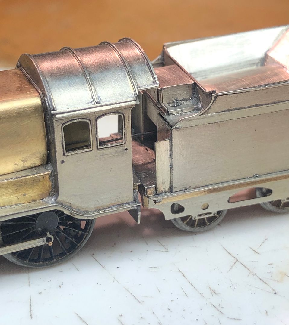
And with the loco. Look how badly the loco has tarnished just sitting at the back of the bench while I worked on the tender.
20191015_085245.jpg

The roof is just "tacked" on with a drop of super glue each side and at the front until I know that the backhead etc can be got in with the roof in place.
20191015_085523.jpg

Cheers,
Peter
 
Last edited:

Ian@StEnochs

Western Thunderer
‘Food’. Is that the drivers piece your fixing with superglue or is it that pesky predictive text poking its nose in again?

Enjoying your thread nevertheless,

Ian.
 

P A D

Western Thunderer
The tender chassis is now fully soldered and simple nickel silver springs have been fitted to the floating centre bearings. They locate into recesses drilled into the bushes to prevent them rotating. The right angle bend at the rear is just to ensure the front of the spring remains vertical whilst soldering.
20191015_151656.jpg


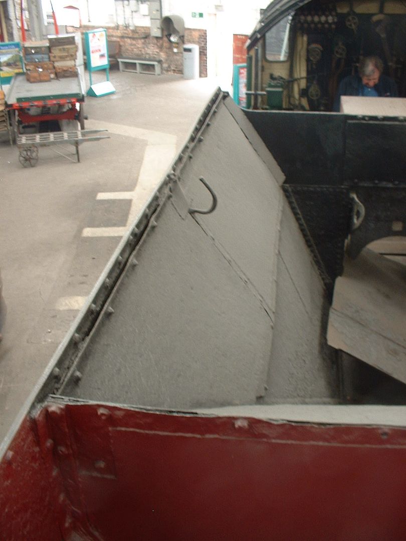
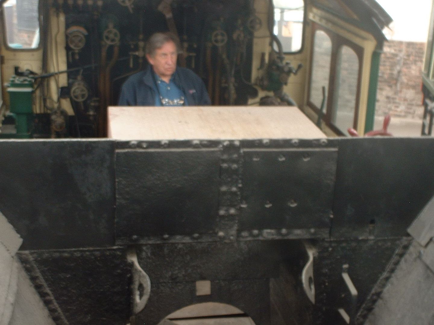
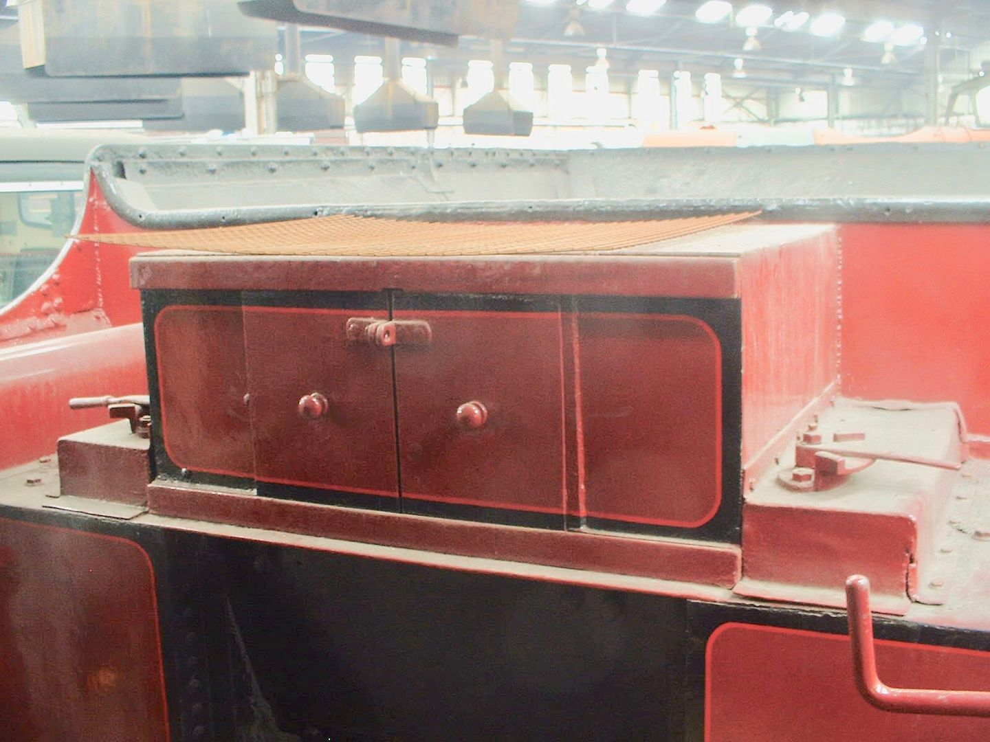
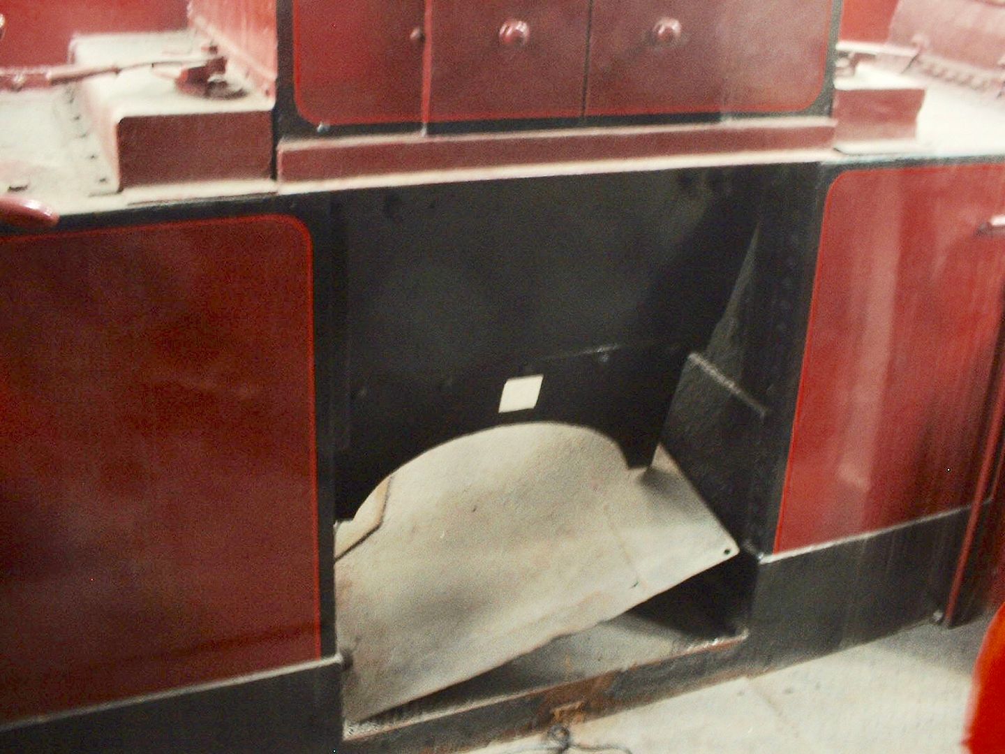
At the front end of the tender, the tool box, coal door and footplate have been added. I'm not sure how the door would work on the real thing or what the purpose of the arched piece at the bottom is.20191015_190850.jpg
20191015_190829.jpg

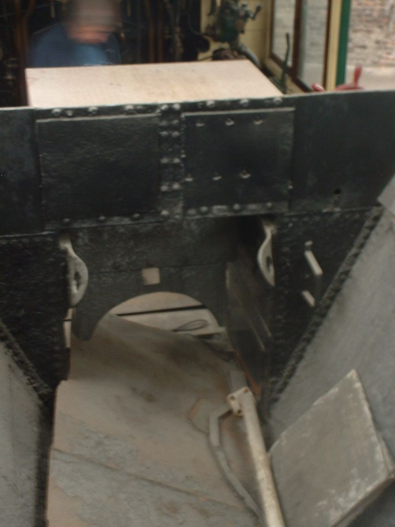
And at the rear, the water filler and water pick up overflow (the tool box looking thing) have been prepared ready for epoxying in place. For now they are just placed for the photo.
20191015_175023.jpg

Cheers,
Peter
 

adrian

Flying Squad
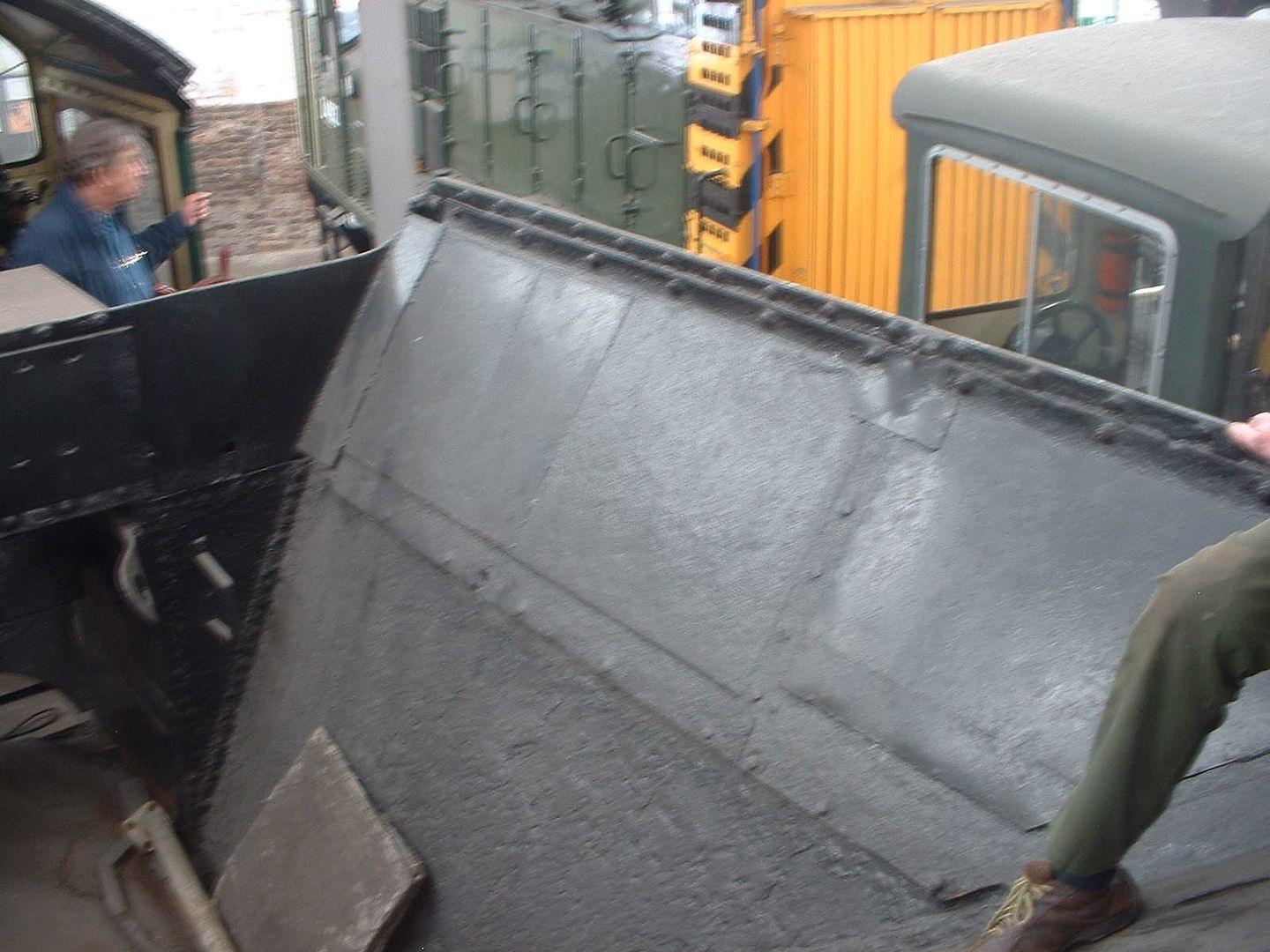
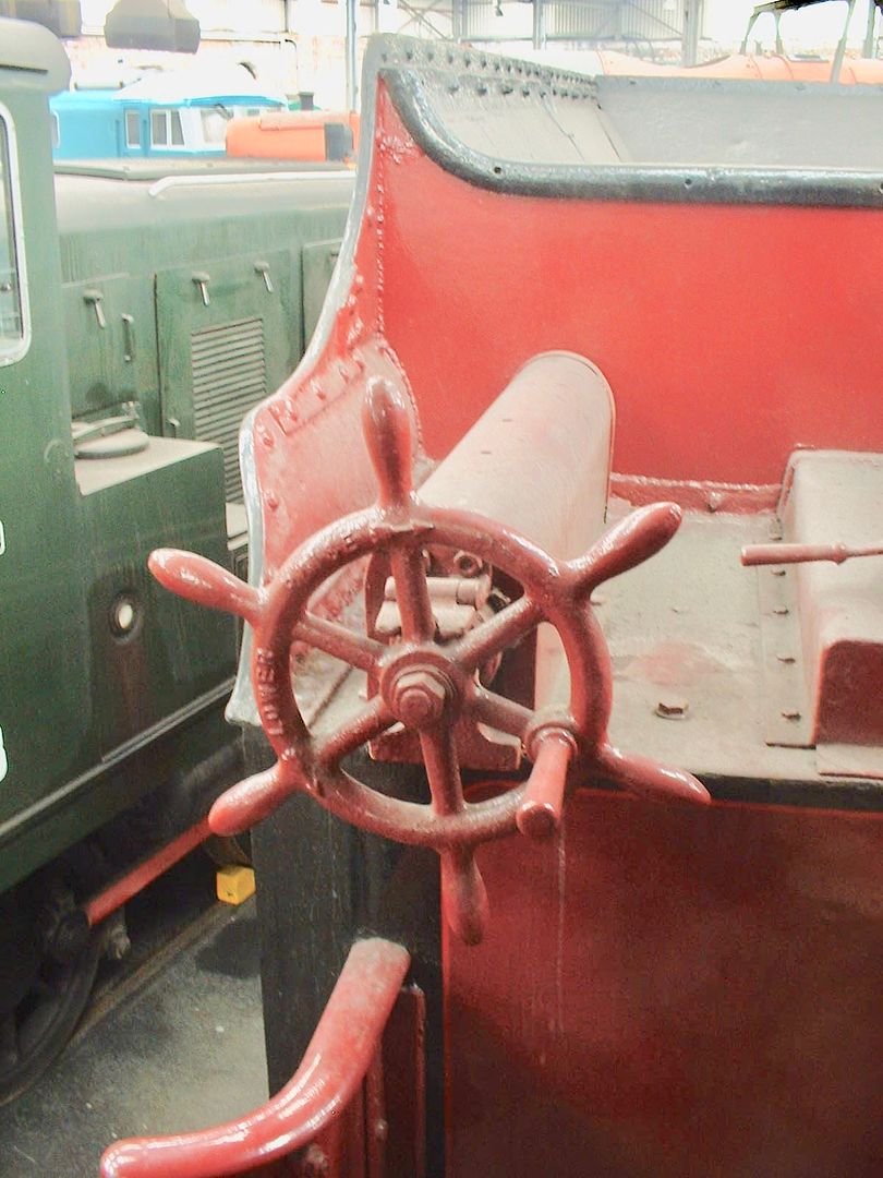
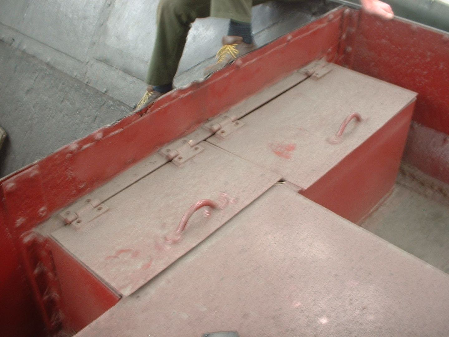
That wheel - penultimate photo - looks distinctly nautical in origin! and the final photo - just who decided it would be a good idea to use the coal space as a slide. :rolleyes:
 

P A D

Western Thunderer
Many thanks Tim.

I found some similar shots on RMWEB, but these have some additional images. I don't know if they were taken by the same chap.

They are very interesting, particularly the sides of the bunker reaching right up to the top of the raves and the water filler/pick up area behind the rear bulkhead. Do you or anyone else know if these are original features, or post GCR days?

The inner end of the water filler with the hinged lid, is narrower than main part and also has a handle, which I note is curved, not as I have done it. Easy enough to correct the handles though. I will also close the gap under the toolbox at the front as I left a gap to represent the bottom of the doors for opening outwards, but of course they are sliding and the bottom strip is the rail. Period photos of the innards of the tender appear non existant, all least in all the searches I have made on Google.

As to the bloke on the slide, well boys will be boys. :D

Cheers,
Peter


Cheers,
Peter
 

LarryG

Western Thunderer
It was immaculate in 1962, but I have to add, very unreal...! Judging by the oversize lettering, it hasn't been repainted since then. D11's don't look real to me unless they are filthy and looking very obese ... ;)
WEB D11 C.jpg
 
Last edited:

oldravendale

Western Thunderer
In fact Butler Henderson had quite a long period running on the GCR, initially in GC livery but latterly in lined black.. Whatever you see now is a subsequent paint job - but it may still be the one in which it left the GCR to go back in to static preservation.

Brian
 

Tim Watson

Western Thunderer
Afraid I’m not much of an expert on anything until I make a model of it, Peter, so the historical accuracy of BH’s tender is beyond my pay grade.
I suspect that the inner top sides did go high, as implied by the upturned lateral ‘horns’ on the front coal plate. That is how I have made mine, although it is still awaiting fixing and so is a bit wonky.
URL=Photo by strq0672]
0CC922D3-2E0D-49E6-8A9B-24F12DD60638_zpssj9tlpte.jpeg
[/URL]
Tim
 

P A D

Western Thunderer
Not to worry Tim.
I'm quite happy to go with the instructions on the water filler and the bunker is done now.

This afternoon I added the beading made from 0.7mm brass rod, clamped to the bench and draw filed on the upper side to make it "half round".20191016_182451.jpg

The beading on the coal plate was also added along with the extension plates either side, plus the beading on top for the handrails. The gap under the tool box has also been filled after seeing the photos posted by Tim Watson.
20191016_182350.jpg


The water filler castings are still loose until I replace the handles on the lids with arched ones.
20191016_182205.jpg

Cheers,
Peter
 

Genghis

Western Thunderer
Lovely clean work as usual, Peter.

Have you ever tried this for beading; comes in various sizes. (Usual disclaimer!)

Jeweler's Brass Half Round Wire (Soft) (NuGold) | eBay

Regards, Deano.
Trisha and I pack this in kits where the packing list identifies that half round is required. I think we need to start doing this in other kits that currently use round wire for beading. The supplier has always given us good service.
David
 

P A D

Western Thunderer
Lovely clean work as usual, Peter.

Have you ever tried this for beading; comes in various sizes. (Usual disclaimer!)

Jeweler's Brass Half Round Wire (Soft) (NuGold) | eBay

Regards, Deano.

Hi Deano,
Yes I bought some after somebody else mentioned it in a recent post (Mickoo I think). It arrived yesterday, but plonker that I am, I ordered the wrong size! I couldn't be bothered messing around changing it, so just got on and did it with rod. It will come in for something and act as a reminder to me to read the description with more care in future.
Cheers,
Peter
 
Last edited:

P A D

Western Thunderer
Moving on to the tender frames, the instructions suggest fitting them to the tank and then fitting the axleboxes and springs. That's fine if you have 6 axlebox/spring castings but in this case, there are 36 separate parts to fit.
20191018_190928.jpg

Therefore I opted to add the parts to the frames before fitting them. Here they are almost finished apart from the shock absorbers for the bottom of the hangers. First I epoxied the axleboxes and then the springs. The spring hanger brackets were then slid into place after first scribing a line with dividers from the top edge of the frame to mark their position. They were then soldered whilst holding them with tweezers. After cutting off the excess from the hangers, I will then epoxy the shock absorbers to the underside of the brackets and then fit the frames to the tank.20191018_190855.jpg

Cheers,
Peter
 

P A D

Western Thunderer
As mentioned earlier, the instructions suggest fitting the frames, then adding the 18 parts each side for the springs and axleboxes. They also suggest making up and adding the steps after the frames are fitted. However, it is far easier to fit the parts to the frames in the flat and also fit the steps to the valances before fitting the frames. Here are the completed frames and steps ready for fitting.
20191021_224844.jpg

Here are the parts after fitting to the tender. There's a half etch groove to locate the frames and all soldering was done on the inside.
20191021_224744.jpg

I hope having the frame detail in place does not cause undue problems during painting, but with so many parts to fit, it would not be practical to leave them off until after painting.
20191021_224646.jpg

And a shot on the chassis.
20191022_212532.jpg

I've replaced the filler/water scoop casing handles on the lids and added tank the lifting brackets. The instructions are a bit vague as to the position of the brackets so if anyone knows better, please let me know. The filler/water scoop casing were epoxied in place and some cleaning up of oozed out resin is still to do.
20191022_212744.jpg

20191021_224305.jpg

I made a start on the brake gear so hopefully that will be done later today.

Cheers,
Peter
 
Top