Building the JLTRT Rebuilt Royal Scot

oldravendale

Western Thunderer
Friends are helping to dig me out of the loco and tender holes!! David - thank you - is sending me the raised footplate parts for the tender so I won't even have to fabricate my own.

And on Friday a small envelope with a Glasgow postmark dropped through the door. I reckon it can only be the casting from Laurie but we'll find out tomorrow - as we're still shielding here mail has to wait three days before we bring it in. If that's the case my epoxy casting exploits will be to no end purpose (which can't be a bad thing). Confirmation will follow tomorrow. I hope there may be a photo or two of progress on the loco footplate too.

Brian
 

oldravendale

Western Thunderer
Yes! The envelope contains the missing casting. :))

My efforts now account for two afternoons of my life that I'll never get back. (Not to mention Mrs D's talcum powder).

I've sent Laurie a thank you note. Exceptional service, particularly as he didn't sell me the kit in the first place.

Brian
 

oldravendale

Western Thunderer
Brian, I have today been clearing up my stocks of part etches (small panels that are needed for kits other than what the main etch provides for) and I have found a couple of Stanier tender raised footplate parts. Happy to send one to you if you need it.
David
Hello again David.

Thank you for the etch. It's perfect (of course)!

Sorry for the delay in acknowledging, but mail goes in to quarantine for three days so I've only just opened it.

It's very much appreciated.

Brian
 

oldravendale

Western Thunderer
Dropped footplate now fitted with frame extensions. I've also fitted the footsteps and their supports with the middle piston cover.

IMG_20200822_165653832_BURST000_COVER_TOP.jpg

I delayed the bending of the smoke deflectors as there is no reference or pattern and they looked a complex shape. However, Heather said that she'd been able to do it with finger pressure so I gathered resources and went for it. I started by joining the top section to the lower using the rivetted strip. Then I created the wider radius top of the deflectors starting with the smokebox as the former, then the 15mm copper pipe to tighten the bend. That done I created the tight bend towards the base over the two smaller radius rods. I reckon it worked rather well!

IMG_20200822_165525076.jpg

Brian
 

oldravendale

Western Thunderer
Smoke deflectors fitted after soldering the internal hand hold domes. The bottom brackets are designed to take a thread so that the deflectors can be (relatively) easily fitted and removed. Once painted I'll make a decision on whether to fit permanently. The brackets, one to the smokebox and a couple to wrap around the handrail are yet to be fitted as their precise location is difficult to determine until the boiler is in place.

Lamp irons also attached. These are the cast brass ones from that nice Laurie Griffin.

IMG_20200825_163335175.jpg IMG_20200825_163401440.jpg

Although the smokebox saddle is yet to fit, so the boiler height is all wrong, it was an opportunity to check the general appearance of the deflectors around the smokebox. There is probably a little more adjustment needed before they are finally in place but they are fundamentally the correct shape and the location is about right.

IMG_20200825_163609455.jpg

There are still a pair of footsteps to fit either side of and outside the deflectors, on the front of the dropped footplate. Once that is done the footplate will be put aside until the frames are made up as the remaining etched fittings - footsteps, buffer beam brackets etc - are either subject to potential damage in handling or need the frames to be fitted to ensure the parts are in the correct location.

So, next on to the frames.

Brian
 
Last edited:

Ian@StEnochs

Western Thunderer
I left the reflectors until late on in the build when the boiler was in place. I used short 16ba screws up into the brackets to permit fitting it after painting. The handrail holds the top and the etched stays just but up to the smoke box but are not fixed permanently to it.

Ian.
 

oldravendale

Western Thunderer
I left the reflectors until late on in the build when the boiler was in place. I used short 16ba screws up into the brackets to permit fitting it after painting. The handrail holds the top and the etched stays just but up to the smoke box but are not fixed permanently to it.

Ian.
Thanks for the comment, Ian. I added the deflectors at this stage only because they are on the drawing which comprises the instructions for this part of the build. They are fitted as you have suggested, ie 16BA screws in to the brackets. In fact they've now been removed to prevent possible damage. The stays will indeed simply have to butt up to the smokebox but the fittings to the handrail will give the final indication of the tweaks necessary to get the deflectors "just so".

Today has been a "removing the cusps" day on frame etches, some of the spacers and also polishing out the join marks on the cast springs. It takes an age! Tomorrow will probably be spent doing some more of the same.

Brian
 

Ian@StEnochs

Western Thunderer
Brian,

Sorry! I read and replied to your post on my phone on the way home on a bus and didn’t notice the screws. Now viewing big time on a tablet!

Cusps and part lines are a real pain and can take up lots of build time. One reason I prefer to build from scratch.

Ian.
 

oldravendale

Western Thunderer
Ian - please don't apologise! It was clear that your comments were intended to be helpful which is how I interpreted them.

But I agree with your comment about part lines......

Brian
 

oldravendale

Western Thunderer
I know it's a while since I posted. The mojo has been a bit lacking and in certain areas this kit has been a trial so far which has not helped. In fact it nearly became a shelf queen for a while, but I suspect if I'd started something else the enthusiasm would remain in abeyance. However, I've received valuable help and input from David Boorman, Heather, David Genghis, Mickoo and Dikitriki, to name but five, and others have come in and out of the story. I'm sure I'll need Ian@StEnochs' assistance, so willingly offered too, given time! The various works drawings have also been really valuable.

Putting together all I've learned it looks as though this had two stages of design, the genesis being an etched construction to which castings were added somewhat later. It is also quite possible that the cast boiler/firebox/smokebox was a latecomer to the party and the castings were a reaction to that. In some areas the etches were not updated to take account of the chassis castings as a result of which locations are not identified or are possibly of the wrong size. I'll try to point these out on the way. There is no doubt that some of these issues are resolvable with care and consideration but some are guesswork. Having read Heather's thread through she had just reached the stage of head scratching over the bogie assembly, one of the areas which is now close to resolution for me.

So, after due cogitation I've grabbed the bull by the antlers, grasped the nettle, larded my goins and gone in again.

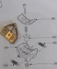
I looked at the castings for the brake cylinder and associated gubbins which is mounted on a rear frame spacer, so this seemed a good way of easing myself back in.

IMG_20200910_143441304.jpg

Comprising about ten or a dozen parts it was a fiddle but actually a joy to construct. Confidence flowed back!!

The tender remains in the state as previously reported but I am now in a position to move that forward. While I was resolving that one, with help, I started on the loco footplate as previously reported and then moved on to the frames. I felt that an understanding of the relationship between bogie and frames would be good if sorted earlier rather than later and this is where the first of the theoretical issues became apparent.

The frame spacers were cut from the etch and a dry run was attempted. On the whole it was good but there is something strange about the attachment of the casting for the bogie to the main frames.
IMG_20200910_143322342.jpg

It's also apparent that there was, at one time, a top spacer as there's a cut out shown on the drawing of the top of the frame etches which is not present on the etches themselves. The cut out as shown on the drawing looks to be the same size as the one at the bottom so was intended to take a tab from spacer G or K. Edit - I think that notional top spacer was used to join chassis to body. Whether it's needed now is another question entirely. However it won't be beyond the wit of man to instal. a spacer later if it turns out to be required.

IMG_20200831_134625037.jpg

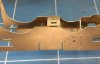
There is a cut out in the bottom of the frames which also fits spacer G or K, but the instructions refer to fitting a casting.

IMG_20200831_134505062.jpg

I interpret that to be so that the loco body will ride and slide on the bogie. Here's the casting in question.

IMG_20200831_134940067_BURST000_COVER_TOP.jpg

and it's considerably longer than the cut out. So should the cut out be widened to the front, to the back , a new cut out filed at the centre - or is a cut out not required at all? There's no help in the instructions. The more I consider this the more convinced I become that the cut out is not appropriate for the castings which should probably be centred.

IMG_20200831_134805980_BURST000_COVER_TOP.jpg

The instructions suggest that the "cast inter frame bogie support" should be bunged in or around the cut out somewhere. Furthermore spacer G has an offset mounting hole, and after some digging and assistance it appears that this was the original bogie support spacer and that the bogie etch, not now used, was pivoted back from the centre. I suspect that the castings have been substituted as the boiler is very heavy and the bogie casting sliding on the bogie support may be the only way to prevent the front of the loco dipping forward. Certainly it will not be possible to provide sufficient weight at the cab end of the loco to compensate the weight of the boiler.

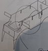
My approach to this has, therefore, been to erect the frames. I can then ensure the bogie is centred on the bogie wheel cut outs. Alternate spacers were squared up and soldered to each side in turn, to equal out any inaccuracies. In fairness these frames are as straight and true as any I've built for any kit in the past.

IMG_20200910_143158023.jpg IMG_20200910_143216523.jpg

If the frames have a weakness it's that, at this stage, the front section waves around in the breeze due to the lack of support. This would be much improved by the presence of the bogie support, but as I don't know exactly where it should go I can't fit it yet. There is an etched spacer to go on the front, behind where the buffer beam will be, but there's no positive location for it. I've fitted and removed it once already as the front of the frames were showing some banana tendencies. That's lack of technique on my part and the next visit to the workshop will see that put right.

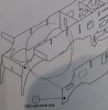
Next is a dry run of the bogie.

It's notable here that there is a single bogie frame spacer, intended to go at the front of the frames. There is no rear spacer, although the casting could be considered a spacer in its own right. The instructions propose a wire of indeterminate diameter and length at the rear of the bogie, although the length will simply be determined by the final width between the frames..

First problem, and of my making, is that the bearings are for 5/32" axles but the axles on the AGH wheels are 3/16". I'm committed to using the AGH wheels so reamed out the bearings to 4.8mm, giving a small clearance for the axles. This left very little meat in the bearings but just about enough for them to work within the hornguides. The beams are screwed in to place with a captive nut on the inside of the bogie frames. Whether this is intended to allow the beams to rock I'm uncertain but the fit between beam and bearing is so tight that I suspect not. The fit of the large central bogie casting is also a matter of guesswork, although the relief inside the casting, where it attaches to the frames together with the relationship of casting to beam tops suggests that the casting is fitted centrally, as does the drawing in the instructions.

Here is the bogie, dry run again, being held together by the wheels which, at this time, make a very effective and gentle clamp.

IMG_20200912_160737316.jpg

My intention is to solder this casting in place. If at a later date it's found to be necessary to move it forward (unlikely) or aft (quite possible) it won't be beyond my ability to unsolder and resolder in the correct location. One imponderable right now is the height at which the front of the loco will ride, having installed the "cast interframe bogie support" so it may be necessary to provide some shim to make the footplate ride higher, or to remove some metal from something to make it ride lower. A secondary issue is that the wheels are very tight with the backs rubbing on the bearings preventing them from rotating freely. This will be easily overcome by reducing the width of the bearings.

So, that's where I am right now. I think I can now see a way forward, although whether that bogie will have enough swing for a 6 ft curve I'm uncertain.

Looking towards the next stage I've released the frame overlays from the etch. These, together with the rest of this sheet, are as oxidised as any I've seen anywhere. This is strange considering that most of the etches are bright and shiny. These will have to be attacked with some physical polish of some sort, possibly a brush in the Dremel.

IMG_20200910_143651464.jpg

Brian
 

Attachments

  • IMG_20200831_134545070.jpg
    IMG_20200831_134545070.jpg
    111 KB · Views: 13
  • IMG_20200831_134726805_BURST000_COVER_TOP.jpg
    IMG_20200831_134726805_BURST000_COVER_TOP.jpg
    101.6 KB · Views: 11
  • IMG_20200831_134545070.jpg
    IMG_20200831_134545070.jpg
    111 KB · Views: 12
  • IMG_20200831_134625037.jpg
    IMG_20200831_134625037.jpg
    91 KB · Views: 12
  • IMG_20200831_134726805_BURST000_COVER_TOP.jpg
    IMG_20200831_134726805_BURST000_COVER_TOP.jpg
    101.6 KB · Views: 12
  • IMG_20200910_143322342.jpg
    IMG_20200910_143322342.jpg
    180 KB · Views: 12
Last edited:

Steph Dale

Western Thunderer
You could use citric acid. Available from a variety of sources, I got mine from here: Cup Alloys - Brazing Ancillaries - www.cupalloys.co.uk
In about half an hour you'll have clean etches; it won't necessarily remove all of the discolouration, but will give a clean 'open' surface for soldering or painting. Beware wire brushing - it'll polish and 'close' the surface, which'll look nice, but it'll be harder to solder or paint.

Might need a chat about chassis set up; you'll remember my email...

Steph
 

oldravendale

Western Thunderer
Thanks Steph.

That's what appears on their web site as "Cleaning Salts", I guess. What about if I just nicked a lemon out of the fridge? No-one will notice.......

In view of your comments I'll avoid wire brushing.

Yep, I remember your email. Having now reached the bogie stage, as described, and with due regard to the castings, I suspect that any sort of traditional set up will not apply, particularly in view of the weight of the boiler.

We can discuss!!

B
 

michael mott

Western Thunderer
Brian, I have just finished reading through your entire build so far. I am not one that usually builds kits except when I was a young lad and could only afford the Airfix airplanes at the local Acton W3 Woolworths for 1/6d which was the extent of my "pocket money" but that is many many moons ago now. It is an interesting journey following along with the way these kits are designed and made. The whole world of metal etched kit work has come a long way since the advent of Cad and experience in the industry. I did a little brass etching when I had my Architectural Modelbuilding business back in the late 70's, not sure that I enjoyed the process much, bit I needed a lot of tiny railings for a parking lot in a multi story building model.

I particularly liked your solution for replicating a missing casting using the Plasticine and epoxy. another good material for replicating tiny parts in plastic is Fimo or Sculpy modeling clay, they are easy to work with and can be baked in a toaster oven then become quite resilient. with simple molds without undercuts the clay can also be used as the mold then baked and used for multiple parts.

Back to your work, I shall continue to follow along and learn about this way of producing a model, The tender is looking good to me. I was also interested to learn about the bending of the curved parts using the steel rods and finger pressure. You also mentioned a building jig/tool that I saw that the tender chassis was sitting on. I am curious about that. Another question about the folding up of the tender inner framework, did you have to use special tools to fold it up or are the folding spots so thin next to the thicker parts that it folds easily without distortion.

Probably too many questions, so Ill leave it there.

Michael
 

Ian@StEnochs

Western Thunderer
Hi Brian,

Sorry to hear that you are having some trials with the Scot. It’s quite a while since I was at the same stage but I have looked out the engine and taken a few pictures which may, or may not, be of some help. My model is in S7 so I needed to make some modifications to the cast spacers.

I made the cylinders removable along with the motion brackets and all the gear. All held down with some screws into additional spacers. Once fitted the front becomes quite rigid. I did add an extra spacer at the front to take the screw which holds the body in place. You can see it in the attached photos.

I built the bogie almost as intended, but widened, and I have put tiny coil springs in recesses milled in the top of the axlebox. I like my engines to ride on the springs, they run smoother and quieter especially over crossings. The springs are remnants of my P4 days and were from the Exactoscale sprung axleboxes. The axles are 5/32” for the S7 group wheels. I used the cast side control springs without modification as they are all but invisible anyway.

The bogie support casting I just cut in half and spliced in some additional support. I made a turned brass centre pivot rather than a screw and added a couple of sprung plungers either side of it. These are just tubes with one end closed off with a buffer shaped ram and coil spring. The bogie retains the ram in place and the loco rides on the springs. As you say the boiler is heavy at the front, it took a bit of time experimenting to get the spring settings correct.

On the rear rod stay on the bogie I soldered a U shaped fork which engages with a corresponding pin on the loco to restrict sideplay, it also stops the bogie swinging sideways and getting fankled. I use this system on my 4-4-0s, and it works well steering the front into curves. On the Scot it didn’t work until I added a bit more weight to the bogie, the lead sheet in the photos. I have found that bogies need to be viable vehicles on their own to actually steer a loco. They need some mass of their own and relying on a spring just isn’t enough.

I hope this is of some help and you get back on track!

Ian.

PS. Viakal removes tarnish from brass without rubbing.

93ED9C7E-BD2F-4AB6-8213-7B26E559A206.jpeg

8E4BA0D3-3B6A-4A8E-A80F-9528786CC56E.jpeg


6BD1F9C9-1803-4083-9E28-4740FC98C79D.jpeg

75ECD0AE-DEC0-4866-93D4-D7DF6E50C2D1.jpeg
 

oldravendale

Western Thunderer
I particularly liked your solution for replicating a missing casting using the Plasticine and epoxy. another good material for replicating tiny parts in plastic is Fimo or Sculpy modeling clay, they are easy to work with and can be baked in a toaster oven then become quite resilient. with simple molds without undercuts the clay can also be used as the mold then baked and used for multiple parts.

Back to your work, I shall continue to follow along and learn about this way of producing a model, The tender is looking good to me. I was also interested to learn about the bending of the curved parts using the steel rods and finger pressure. You also mentioned a building jig/tool that I saw that the tender chassis was sitting on. I am curious about that. Another question about the folding up of the tender inner framework, did you have to use special tools to fold it up or are the folding spots so thin next to the thicker parts that it folds easily without distortion.

Probably too many questions, so Ill leave it there.

Michael

Thank you, Michael. I much appreciate your comments about Fimo and Sculpy. I'm familiar with Fimo - not that I have any - but I've not seen Sculpy as far as I'm aware. To be honest, as I hope I implied, the use of epoxy resin and Plasticine was only a qualified success and the whole process needs considerable refinement. I reckon it'd be OK, but no better than that, after some further work.

The chassis jig is by Hobby Holidays - Master Chassis from Hobby Holidays

Phil Atkinson, the proprietor, lurks on here from time to time. If you are interested it's worth giving him a call.

There are many on this forum who make long 3/16" rods passed through the bearings and squared up on graph paper work well. I've never been terribly successful with that and the Hobby Holidays jig has helped me produce square chassis. Equally, there has been a single occasion where, for one reason or another, I got it wrong and a chassis was out of square. That was down to me not using the tool correctly in the first place!

As for folding, for many years I used angle aluminium in a bench vice against which to bend components. It works well enough where there is a half etched mark at the position of the bend and if the part being bent is not too long. Proper bending bars are available, designed for the bending of brass and nickel silver and which have one component slightly more than a right angle so that the tendency of the brass to spring back, just a little, is compensated for in the process of bending. I also use a "Hold and Fold" - see Hobby Holidays Hobby Holidays product details This is a really convenient and quick tool for bending and is good for 90% of cases where a crisp fold is required. I used a combinatiion of these tools on the tender framework where the folding lines enable really crisp and distortion free bends to be created. I decent engineers' square is also quite important to check that bends are at 90 degrees.

I'm sure you'll find that there will be a number of alternative processes championed by other contributors to the august organ and, as with all such things, you have to find the method which suits you.

Hi Brian,

Sorry to hear that you are having some trials with the Scot. It’s quite a while since I was at the same stage but I have looked out the engine and taken a few pictures which may, or may not, be of some help. My model is in S7 so I needed to make some modifications to the cast spacers.

I hope this is of some help and you get back on track!

Ian.

PS. Viakal removes tarnish from brass without rubbing.

Thank you Ian. That is an amazingly concise set of comments which will certainly help me on my way. From my own perspective I'm pleased to see that it looks as though I was heading in the right direction but these details have given me confidence to move forward and also some thoughts about improving the bogie and its guiding characteristics.

I'll press on (maybe not today - it's too 'ot!) and will keep my reports coming.

To all who have commented in any way - your help has been incredibly useful. I never cease to be amazed at the experience and advice so willingly shared on this forum.

Brian
 
Top