Scratch build - LNWR Precursor Tank - Scale7

adrian

Flying Squad
Finally decided to break cover with my second scratchbuild project. A few hints have been dropped over the year and I'll be oscillating between this and the Sentinel build as the mood takes me.

So project No.2 is a Precursor Tank - I'm still not sure why. I just fancied building something pre-grouping and being a member of the L&Y Soc. and the L&NWR Soc. I was flicking between the 2 companies for the next build. Having seen some LNWR loco's and stock at last years Scale7 North meet I settled on the Precursor Tank, the final decision was due to the excellent digital archive of the L&NWR Soc. from where full GA drawings where available to members which is a boon for scratch building.

So yes I'm aware there are kits available but as I always seem to end up modifying them in someway I decided to go back to my roots and do a pure scratch build project. I have also decided to do a full blow by blow account of the build to show that scratch building is not difficult and having dealt with a few ropey kits I still maintain that any competent kit builder would have no problem scratchbuilding.

So this time in the correct wheel arrangement, a set of Slaters wheels were purchased and turned to Scale7 standards.
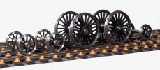
precursor-bogie - 1.jpeg

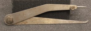
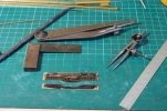
I decided to start with the front bogie as I always prefer to get a rolling chassis before starting on any bodywork. A couple of strips of nickel-silver are soldered together and marked with engineering blue (a.k.a. a sharpie pen!) so that the marking out can be easily seen. The bogie will be fully sprung and compensated, as close to prototype as possible - hence marking out the hornguides as rectangular rather than a circular hole for a brass bush. Nothing more complicated is required than a scriber, a square, odd-leg calipers, dividers and a 6" rule. When looking at the GA drawings it is quite often easy to spot where the original draughtsman set the origin for his dividers as there is a dot on the drawings, this allows me to work out the correct radii for many of the curved sections.
precursor-bogie - 2.jpeg

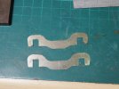
A little time with the piercing saw and fettling with needle files gives me 2 bogie sideframes.
precursor-bogie - 3.jpeg

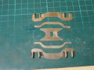
The axles will be fitted with miniature ball races held in a little 3D printed carrier. So brass angle is soldered to the side frames. A length of 5/16" bar is used to space the angle when soldering to ensure the horn guides are parallel and correct separation. The compensation beams and frame spacer are also cut out from n/s sheet.
precursor-bogie - 4.jpeg

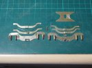
On the prototype the springing is done by means of a leaf spring from a central angle bolster, I'm not convinced leaf springs (or coil springs for that matter) scale very well so I usually look to using wire springs if I can ( hence continuous springy beams etc.) So the plan here is to have the central bolster to provide compensation and then hide the wire springing inside the compensation beam with a dummy leaf spring to hide it.
precursor-bogie - 5.jpeg

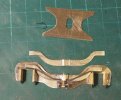
The wire spring feeds through a central brass block acting as the fulcrum point - the end of the wire then rests on the top of the axle hornblock. The slot in the frame spacer is curved, again matching the GA drawing and I intended to fit a side control spring - hence the slot rather than a simple bogie pivot.
precursor-bogie - 6.jpeg

So the bogie side frames and frame spacer soldered together.
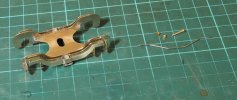
precursor-bogie - 7.jpeg

There are half a dozen other L&NWR loco's I'd like to build at some point and there are several common components used across the different classes so the experience and thought in building this should make it easier for any subsequent builds, which would be easier if there was a set of good quality tender kits available.
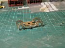
precursor-bogie - 8.jpeg
 

mickoo

Western Thunderer
Watching ;)

I’ve done a set of etched inside motion to correct the LG errors as his joy valve gear is not right for the precursor. You still need the LG packs for some of the castings but all the rods and linkages are quite horrible castings to be honest.

Kind of defeats scratch building but if you’d like a set then just say, I’ll not be offended if you choose not to.
 

simond

Western Thunderer
Also watching.

I “scratch built” my 28xx, but used one of Warren Shepherd’s Hall boiler etches, as it just made sense. If I’d been smarter, I’d have remade the firebox wrapper, rather than modifying it, but then if my auntie, etc…
 

adrian

Flying Squad
Watching ;)

I’ve done a set of etched inside motion to correct the LG errors as his joy valve gear is not right for the precursor. You still need the LG packs for some of the castings but all the rods and linkages are quite horrible castings to be honest.

Kind of defeats scratch building but if you’d like a set then just say, I’ll not be offended if you choose not to.
Many thanks for the kind offer - I will though politely decline. It is unfortunately one of my "soap-boxes" - it's more effort but I prefer to make rods and motion in steel. The plan for this build is to make dummy motion to fill the visible gap inside the frames but it won't be working. The additional effort to get it working I'd rather spend on the visible parts of the loco. I fitted inside motion to the 3F but it just made it harder to get a smooth running loco, so the motion is just floating now. When the loco is stationary there will be sufficient detail to fill the gap and when in motion I don't believe it will be apparent that the inside motion isn't!
 

Ian@StEnochs

Western Thunderer
Finally decided to break cover with my second scratchbuild project. A few hints have been dropped over the year and I'll be oscillating between this and the Sentinel build as the mood takes me.

So project No.2 is a Precursor Tank - I'm still not sure why. I just fancied building something pre-grouping and being a member of the L&Y Soc. and the L&NWR Soc. I was flicking between the 2 companies for the next build. Having seen some LNWR loco's and stock at last years Scale7 North meet I settled on the Precursor Tank, the final decision was due to the excellent digital archive of the L&NWR Soc. from where full GA drawings where available to members which is a boon for scratch building.

So yes I'm aware there are kits available but as I always seem to end up modifying them in someway I decided to go back to my roots and do a pure scratch build project. I have also decided to do a full blow by blow account of the build to show that scratch building is not difficult and having dealt with a few ropey kits I still maintain that any competent kit builder would have no problem scratchbuilding.

So this time in the correct wheel arrangement, a set of Slaters wheels were purchased and turned to Scale7 standards.
View attachment 195559

I decided to start with the front bogie as I always prefer to get a rolling chassis before starting on any bodywork. A couple of strips of nickel-silver are soldered together and marked with engineering blue (a.k.a. a sharpie pen!) so that the marking out can be easily seen. The bogie will be fully sprung and compensated, as close to prototype as possible - hence marking out the hornguides as rectangular rather than a circular hole for a brass bush. Nothing more complicated is required than a scriber, a square, odd-leg calipers, dividers and a 6" rule. When looking at the GA drawings it is quite often easy to spot where the original draughtsman set the origin for his dividers as there is a dot on the drawings, this allows me to work out the correct radii for many of the curved sections.
View attachment 195558

A little time with the piercing saw and fettling with needle files gives me 2 bogie sideframes.

View attachment 195557

The axles will be fitted with miniature ball races held in a little 3D printed carrier. So brass angle is soldered to the side frames. A length of 5/16" bar is used to space the angle when soldering to ensure the horn guides are parallel and correct separation. The compensation beams and frame spacer are also cut out from n/s sheet.
View attachment 195556

On the prototype the springing is done by means of a leaf spring from a central angle bolster, I'm not convinced leaf springs (or coil springs for that matter) scale very well so I usually look to using wire springs if I can ( hence continuous springy beams etc.) So the plan here is to have the central bolster to provide compensation and then hide the wire springing inside the compensation beam with a dummy leaf spring to hide it.
View attachment 195555

The wire spring feeds through a central brass block acting as the fulcrum point - the end of the wire then rests on the top of the axle hornblock. The slot in the frame spacer is curved, again matching the GA drawing and I intended to fit a side control spring - hence the slot rather than a simple bogie pivot.
View attachment 195554

So the bogie side frames and frame spacer soldered together.

View attachment 195553

There are half a dozen other L&NWR loco's I'd like to build at some point and there are several common components used across the different classes so the experience and thought in building this should make it easier for any subsequent builds, which would be easier if there was a set of good quality tender kits available.

View attachment 195552
Adrian,

That is a neat solution to bogie springing. I too have used wire but always fitted them inside the frames, next time I will try your method.

I have quite a few 4-4-0s, my first in S7 had quite a lot of sideplay with spring control, plus a sprung centre pivot. It works well but took a lot of fiddling to get the correct balance.

More recent builds have very little sideplay, very softly sprung, still with sprung centre, but the bogie is made as heavy as possible. The centre pivot spring is arranged to act as low down, as far below axle centres as possible, reducing the tendency for the bogie to tip on curves. They work just as well and take less time to make.

The bogie has to be a viable vehicle on its own so to get enough weight to load the springs I use 1/8" brass flats for the centre strechers. Extra thickness not apparent at normal viewing distances..

Ian.
 

Mike W

Western Thunderer
I think you are right Adrian. I have LNWR locos with working Joy valvegear in 4mm, 7mm and Gauge 3. Especially when in mid gear the movement on the valve rods is tiny and everything else is low down. You might however see the anchor link bobbing up and down below the frames and that 1) wouldn't need any precision work, 2) would fool most people into thinking that it all works!

Mike
 

jonte

Western Thunderer
Apologies: I’ve only just discovered this, Adrian.

Your methods will prove invaluable to satisfying my curiosity as I’ve always wondered how this sort of engineering is done.

Thanks for sharing.

Jon
 

adrian

Flying Squad
More recent builds have very little sideplay, very softly sprung, still with sprung centre, but the bogie is made as heavy as possible. The centre pivot spring is arranged to act as low down, as far below axle centres as possible, reducing the tendency for the bogie to tip on curves. They work just as well and take less time to make.
Thanks for the advice, I hope I'm following a similar route. I'll take a couple of photo's but the plan is to fit limited side springing on the bogie but the centre pivot I was thinking no centre pivot vertical spring, relying just on the vertical springing built into the hornblocks. The centre pivot will only have side control springs.
I have LNWR locos with working Joy valvegear in 4mm, 7mm and Gauge 3. Especially when in mid gear the movement on the valve rods is tiny and everything else is low down. You might however see the anchor link bobbing up and down below the frames and that 1) wouldn't need any precision work, 2) would fool most people into thinking that it all works!
Thanks for the feedback, looking at the valve-gear arrangement whilst the anchor link movement might be the most significant movement if I have it correct in my mind this is below the frame, so whilst a nice to have feature I'm not sure the effort vs reward is sufficient.

Apologies: I’ve only just discovered this, Adrian.

Your methods will prove invaluable to satisfying my curiosity as I’ve always wondered how this sort of engineering is done.
Thanks - there's nothing complicated or mystical about it. I often contend it's easier to scratch build than build some kits. Hopefully the build will encourage others to have a go.
 

adrian

Flying Squad
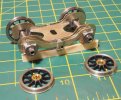
A little more work on the bogie, as shown in the photo I have 3D printed an axle cradle to hold a miniature roller bearing with a lug on the top to locate the spring wire.

precursor-bogie-1 - 3.jpeg

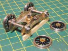
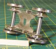
From underneath - this is the arrangement for the centre pivot and side spring control. The plan being to have a length of spring wire located in the copper tube bent in a V form to rest against the brass centre pivot which has a recess turned to hold the wire in position. Also note the 14BA nut and bolt on the bottom of the horn block guides to hold the axle boxes in place. This is copied to emulate the full size prototype - there is a little more detailing to do as looking at the drawings and photo's there is a stretcher bar between these two bolts - I'll make these up later from a bit of thin tube and wire.

precursor-bogie-1 - 4.jpeg

Hopefully this view shows the compensation beam with the internal spring wire resting on the 3D printed axle box.

precursor-bogie-1 - 2.jpeg

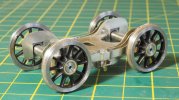
So this is the current state for the front bogie.

precursor-bogie-1 - 1.jpeg

Thoughts now turn to the frames - however to sort out horn guide placement I need to make the coupling rods first - next instalment!
 

Ian@StEnochs

Western Thunderer
Adrian,

I tried a rigid, not sprung, centre pivot on a 4-4-0 relying on the bogie axlebox springs and it didn't work. For me! It was easy to change to a sprung centre and with no other changes the setup performs well.

Thinking through the reason for failure I concluded it was because I try to spring all the axles with differing rates depending on the position. The front driver on 4-4-0s has the stiffest spring and carrys most weight, which tends to lift load from the bogie, hence why I load the bogie itself.

On a 4-4-2 you will be able to load both driving axles equally so that will change the dynamics and your setup could work.

Ian.
 

Richard Gawler

Western Thunderer
Thoughts now turn to the frames - however to sort out horn guide placement I need to make the coupling rods first - next instalment!

Adrian, if you could possibly take some photos of how you mark out the coupling rods and hold them and drill them then I would find this a great help. I am already envious of your zero incumberance by instructions, you know how you expect the parts to go together ;)
 

OzzyO

Western Thunderer
Hello Adrian,

nice looking bogie, it may just be the photo but one of the spring wires looks like it's jut resting on the horn guide.
As you mentioned that your thinking of doing more L.N.W.R. locos and that a number of parts are common amongst some of the classes. For these I'd be very tempted to make jigs for them. The jigs will take a bit of time but will pay for itself when you've made two or six parts.

ATB

OzzyO.
 

WM183

Western Thunderer
Ok. Popcorn ready. This is amazing so far. Did you say the LNWR society makes GAs available to members? Are the Coal tanks, 5' passenger tanks, and so on available too?
 

Mike W

Western Thunderer
Ok. Popcorn ready. This is amazing so far. Did you say the LNWR society makes GAs available to members? Are the Coal tanks, 5' passenger tanks, and so on available too?
They should have all of them. Send a message via the website. If they don't, then come back to me as I have most too.

Mike
 

mickoo

Western Thunderer
They should have all of them. Send a message via the website. If they don't, then come back to me as I have most too.

Mike
You can of course also browse the archives yourself, given that there are thousands of drawings it does take some time, but at least you can see what you’re getting before hand. I think pretty much any LNWR engine and a lot of stock is available but it’s all downloads, not paper copies.

You don’t have to be a member, I’m not and have spent quite a bit so far, but, being a member makes them cheaper. Non members are £5 a drawing and it doesn’t take long to rack up the bill, well it didn’t in my case.
 

Rob Pulham

Western Thunderer
Nothing more complicated is required than a scriber, a square, odd-leg calipers, dividers and a 6" rule. When looking at the GA drawings it is quite often easy to spot where the original draughtsman set the origin for his dividers as there is a dot on the drawings, this allows me to work out the correct radii for many of the curved sections.
View attachment 195558
This part of Adrian's opening post, specifically the mention of the odd leg callipers for which I have to thank him, kicked me up the backside a bit to stop my lazy habit of using measuring callipers to scribe my marking out.

A quick look on the web revealed that I could get some Chinese odd leg callipers for under a tenner but already possessing a set of Chinese (or indeed they might be Indian) cheap callipers which are crude to say the least I thought I would have a look on eBay for some second hand named brand alternatives to see what was/is available. Now one of my favourite Sheffield made brands are Moore and Wright so I started there.

Searching Moore and Wright odd leg callipers brought up quite a selection even some new ones. Many of the cheaper end of the buy it now examples were simply two pieces with one leg bent and the other sharpened. Having seen Adrian's set I rather fancied a set that had a separate scribe pin. I was a bit short of time so I put a couple on watch and returned to them the day after. As it turned out it was the same seller selling both of them and overnight I had received Offers on them. The offered reduction was only a couple of quid but it meant that the better of the two pairs that I was watching came in at £10 posted.

This is what I got for my tenner. A rub over with Scotch Brite and WD40 and they will be as good as new. I am well pleased with them and will enjoy using them for many years to come

53202850117_f13d9b376a_4k.jpg

53204150755_4ff5bdc368_4k.jpg

The arrow alongside the date leads me to think that they are ex military

Each time I use them I will think of Adrian, and his unbeknownst kick up the pants.

This would have been an edit but I forgot to click post reply before applying the Scotch Brite. They have cleaned up as I imagined and while doing so I found a couple of small dings which I smoothed out with a diamond stone so they are now as good as they can get.
 

Mike W

Western Thunderer
Adrian makes a brilliant point about seeing where the draughtsman's compass point had been, and establishing the centre that way. I have done that too and it is one reason I'd rather have a 1.5in/1ft copy of the original drawing than a scanned image that has been "cleaned up" by a well meaning enthusiast.

Mike
 

adrian

Flying Squad
Thanks for all the feedback and comments it is appreciated. I'll try to catch up with all the points raised. Please shout out if I've missed anything.
Thinking through the reason for failure I concluded it was because I try to spring all the axles with differing rates depending on the position. The front driver on 4-4-0s has the stiffest spring and carrys most weight, which tends to lift load from the bogie, hence why I load the bogie itself.

On a 4-4-2 you will be able to load both driving axles equally so that will change the dynamics and your setup could work.
Thanks for the advice - no doubt I'll repeat the same mistakes so I'll build in the option to add springing if required. My favoured springing is the continuous springy beams so it will need a little thought and option to alter it to get the balance right.

Any advice or recommendations for the rear carrying wheel? It was a radial axlebox so I'm still deliberating on how to make it and retain some easy springing.
Adrian, if you could possibly take some photos of how you mark out the coupling rods and hold them and drill them then I would find this a great help. I am already envious of your zero incumberance by instructions, you know how you expect the parts to go together
I will do my best, it really isn't anything special. You credit me with too much regarding the instructions, the way I see it I have the ultimate set of instructions. The GA drawing is the instruction for the original loco - you can't get better than that. Instructions from kit manufacturers are like Chinese whispers - in that they are their interpretation of how the loco was built so you have to figure out not only how the prototype was built but also how the kit manufacturer decided to model the prototype, so in many ways GA drawings are easier.
As you mentioned that your thinking of doing more L.N.W.R. locos and that a number of parts are common amongst some of the classes. For these I'd be very tempted to make jigs for them. The jigs will take a bit of time but will pay for itself when you've made two or six parts.
I thought about it briefly having made jigs in the past but not convinced - was there anything specific you were thinking about? The reason for my reticence is that inspired by Mickoo's work the plan is to 3D model and print various components so repeat items are simply made by loading the file into the 3D printer again. Platework like the bogie and main frames have been drawn out in CAD so easy enough to print and cutout for the next one, even experimented and found it's possible to laser etch the outline directly onto nickel-silver sheet. So not sure what if any benefits from making jigs.
Did you say the LNWR society makes GAs available to members? Are the Coal tanks, 5' passenger tanks, and so on available too?
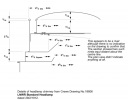
The LNWR Soc. digital archives are a wealth of information, drawings, photos etc all free to members. As Mickoo has noted it's probably cheaper in the long run to join the Society than pay for individual items. They produce a nice top quality society magazine, including a regular modelling supplement. A quick scan for "coal tank" returned 712 "documents" i.e. lots of photos and everything ranging from the following detail of the chimney headlight.
Screenshot 2023-09-21 at 23.25.34.png

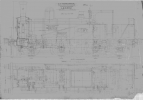
to a full GA drawing
Screenshot 2023-09-21 at 22.44.45.png

This is what I got for my tenner. A rub over with Scotch Brite and WD40 and they will be as good as new. I am well pleased with them and will enjoy using them for many years to come
Excellent - mine are M&W as well - good quality tools are always useful and last. Predominately used to mark out a parallel line when marking out by setting it to the correct spacing on a steel rule and then transferring it to the metal, but also from time to time when needing to transfer a spacing from one component or part to another.
Adrian makes a brilliant point about seeing where the draughtsman's compass point had been, and establishing the centre that way. I have done that too and it is one reason I'd rather have a 1.5in/1ft copy of the original drawing than a scanned image that has been "cleaned up" by a well meaning enthusiast.
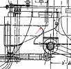
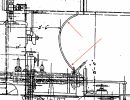
Thanks for picking up on that - yes to illustrate the point I've been drawing out the frames for the Precursor Tank - this is taken from the GA drawing (courtesy of the LNWR Soc! :thumbs:) as indicated although it is not dimensioned it is not difficult to work out the radius centre point from the marks on the drawing.
Screenshot 2023-09-21 at 22.48.33.png

Likewise when it comes to the body work the cab side sheets. When I try to draw out the rear curve on the side sheet there are a couple of marks that on the drawing suggest a very good starting point for marking out the upper and lower radii.

Screenshot 2023-09-21 at 22.48.58.png

I hope that helps and answers any questions.
 

NickB

Western Thunderer
I'd rather have a 1.5in/1ft copy of the original drawing than a scanned image that has been "cleaned up" by a well meaning enthusiast.

The trouble is, I can't find room for a 1.5in/1ft drawing in my workshop! These days I find it so much easier to work off the computer screen.

Nick
 
Top